


What is your project about?
This is the triangle. Which will try to balance itself. With the help of all the sensors & actuators on board.
Why did you decide to make it?
To make a balancing robot without using the MPU-6050 IMU. Instead, used a conventional ultrasonic sensor.
How does it work?
It is an Inverted Triangle. With counterweight on the servo motor to balance itself. And an ultrasonic sensor to detect the falling direction.
When the triangle is upright, its center of gravity remains right above its base. If the triangle falls left, then the CG Shifts left. And moves beyond the base. so the triangle tips over. The same goes for the right side.
So, to keep it balanced. We have added a servo motor. With counterweight on its shaft.
Now if the triangle falls on one side, The servo motor will move the weight to the opposite side. So their combined CG remains at the same place.
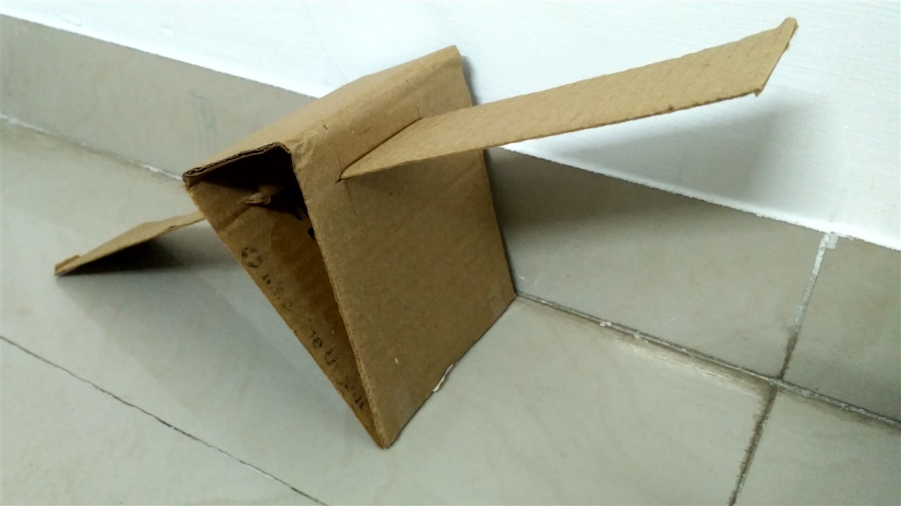
Scrap Cardboard Box

Take a scrap cardboard box. Cut it as per your requirement. Then fold it to form a prism shape. Stick it with tape. This will be the body or fuselage of the robot. We will mount a Servo motor on top of it. The wings will be inserted into their sides.
Cutout Wings
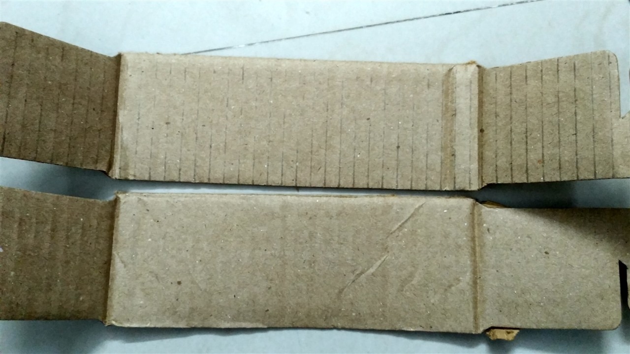
From the same cardboard box cut out two longer pieces for making wings.
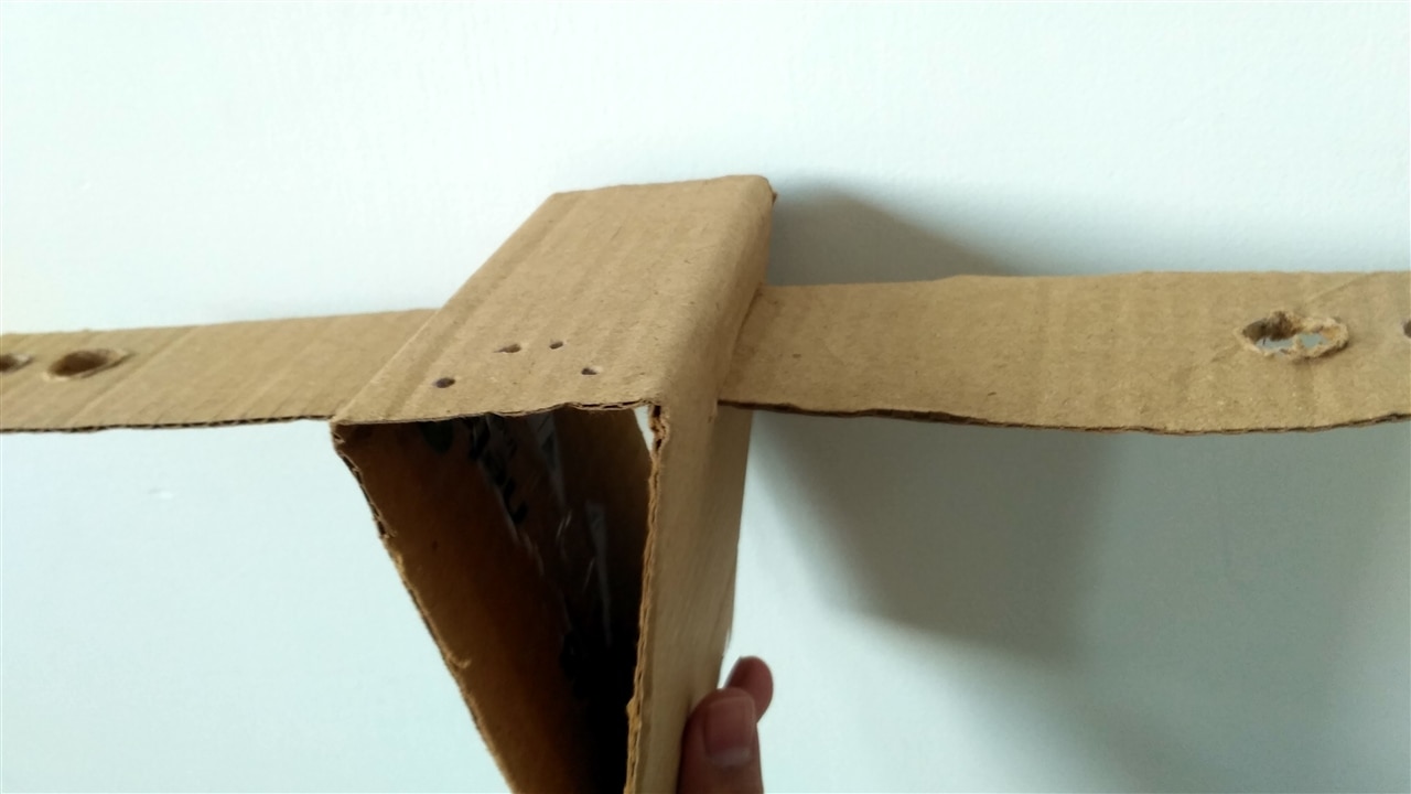
Join Wings With Fuselage
Make holes on either side of the fuselage. The dimensions of the hole must be equal to that of the wings.
Make Holes in Fuselage
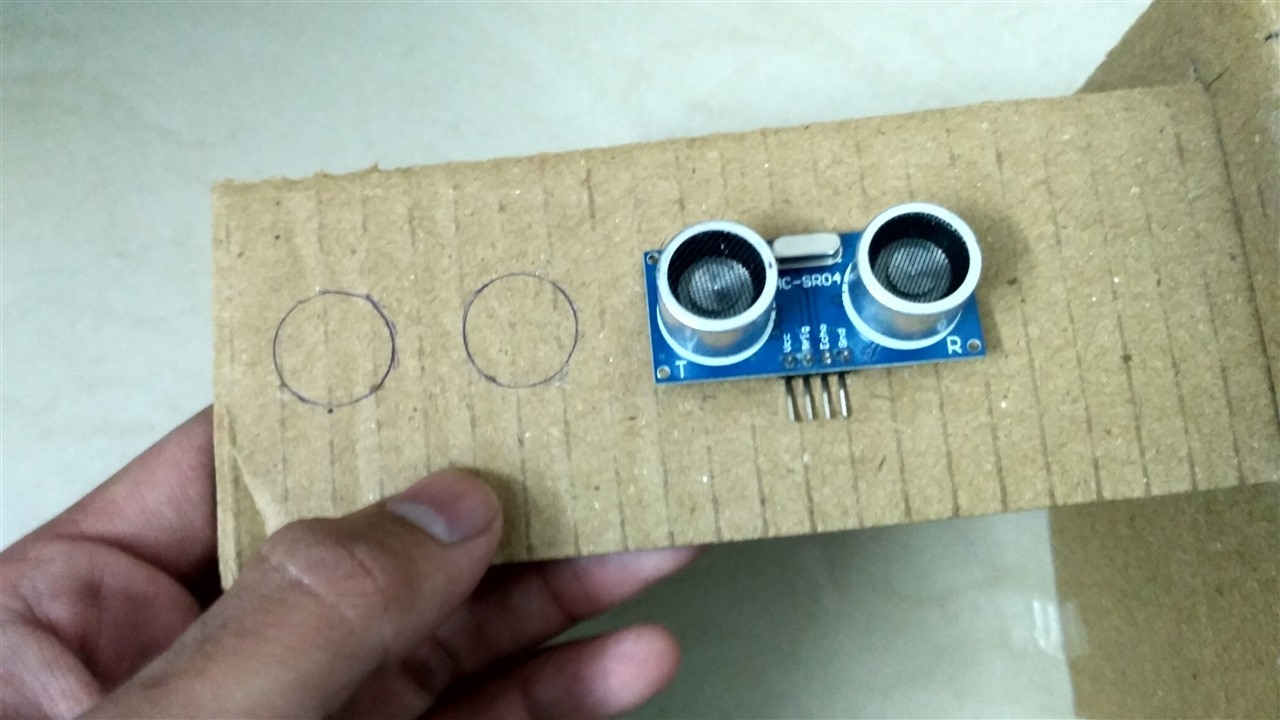
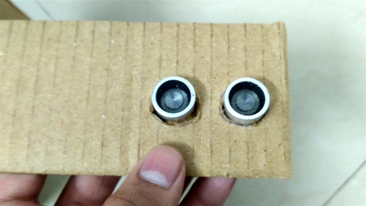
Take reference to an ultrasonic sensor and make some marking on the wings. These markings need to be cut out and the sensor will be inserted into them.
Ultrasonic Sensors
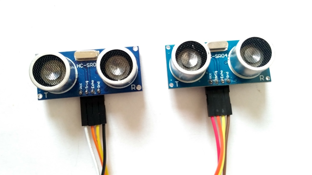
Take two ultrasonic sensors. There are two sensors. But, the other sensor is just for equal dead weight, it is not connected.
Inserting Ultrasonic Sensors
Inserted these sensors into the holes on the wings.
After Inserting Sensors
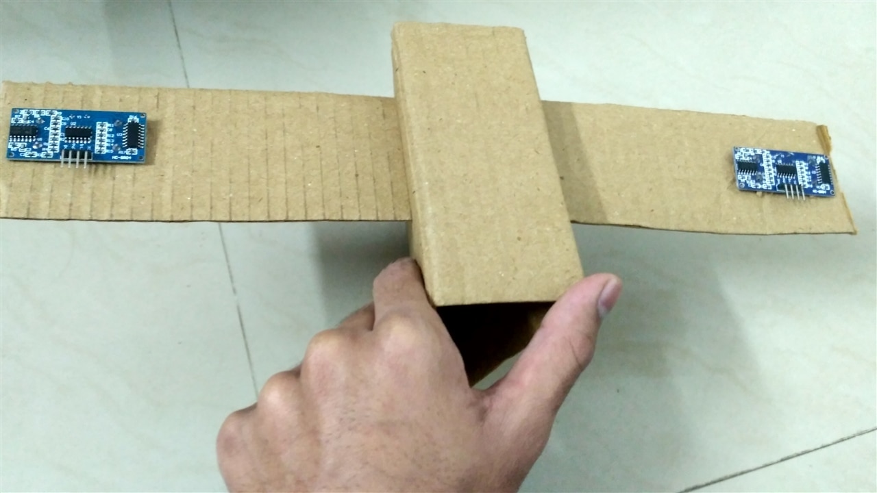
This is what it looks like after inserting sensors on both of its wings.
The Servo Motor With Link Attached

Take a servo motor. Take a long metal link and attach it to the horn on the servo motor. Some weights can also be attached to this link.
Making Holes in Fuselage
Make some holes in the fuselage to mount a servo motor.
After Attaching All Sensors & Actuators
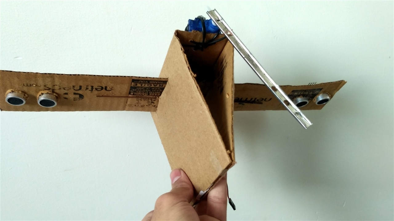
Attach the servo motor on the fuselage with the help of a string/ zip tie/ wire.
Circuit Schematic & Simulation TinkerCAD
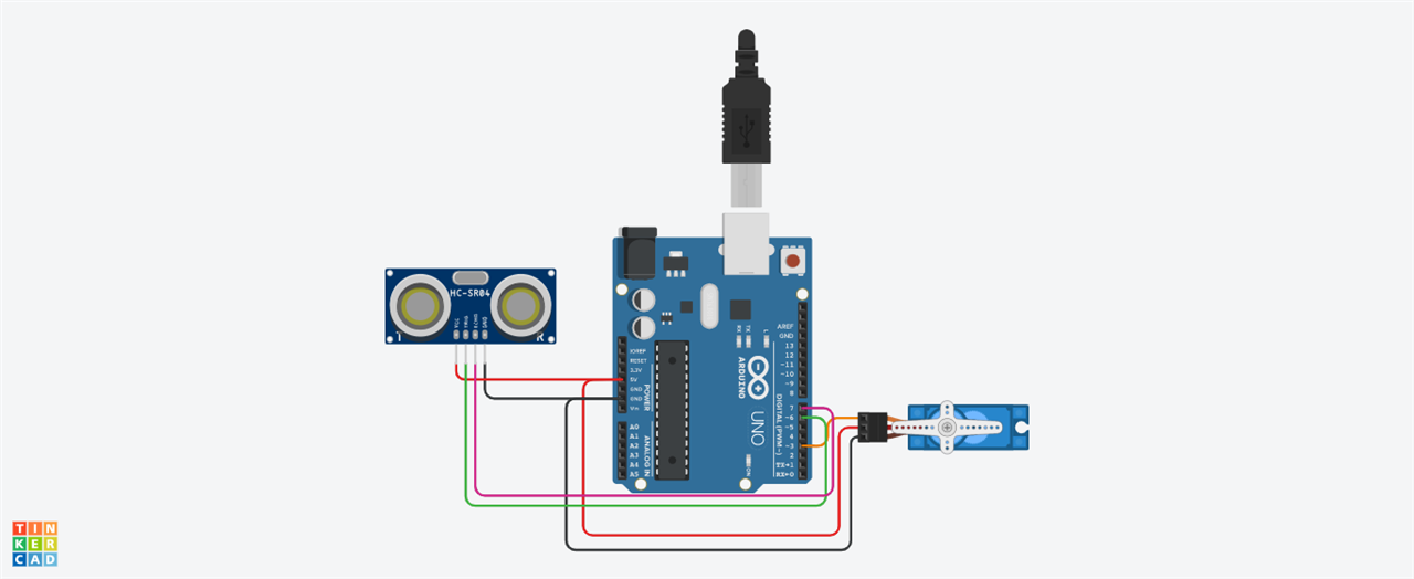
This is the circuit schematic of the self-balancing triangle.
Interfacing With Microcontroller
Write the code and upload it to the microcontroller.
The code should have logic such that whenever the triangle falls on the left side, the link is moved right. And whenever the triangle falls towards the right, the link should be moved left. To counterbalance.
Working
When the triangle is upright, its center of gravity remains right above its base.
If the triangle falls left, then the CG Shifts left. And moves beyond the base. so the triangle tips over. The same goes for the right side.
We have added a servo motor. With counterweight on its shaft. Now if the triangle falls on one side, The servo motor will move the weight to the opposite side. So their combined CG remains at the same place.
Conclusion
We are not able to balance the triangle. But no regrets. We will modify it further. to make it balance itself in its next version.
Code
#include <Servo.h>
Servo m;

int t = 6;
int e=  7;
double d,dp=0;

void setup() {

  pinMode(t, OUTPUT);  //trigger pin
  pinMode(e, INPUT);  //echo pin
  m.attach(3);       // motor at pin 3

}

int distance(){

  long duration, cm;

  digitalWrite(t, LOW);
  delayMicroseconds(2);
  digitalWrite(t, HIGH);
  delayMicroseconds(5);
  digitalWrite(t, LOW);
  duration = pulseIn(e, HIGH);


  cm = duration/ 29 / 2;

  return cm; //returns distance in centimeters
}

void loop() {

  d = distance();

  if(d<18 && d>0){
    m.write(180 - ((dp*0.95 + d*0.05)*10));

  }

  dp=d;
  delay(25);
}
CAD

Schematic


