
Happy Holidays to all and a big thanks to the E14 Elves for sending over a christmas present
For this blog, I decided to write about a custom Camper Van conversion that I built as a present for my father. He has long talked about his dream to drive to Florida and drive around and play music. He is from Michigan and has played guitar for about 60 years. He wanted a stealth van that he could park anywhere incognito and have room for his music gear, while having a hotel on wheels. This build is mostly mechanical, but there were some really fun electrical components as well. This required building a solar charging system, power distribution system, complete wiring harness for the "RV" portion of the van, plus some hacks to make the system better and more functional. (also mechanically building the entire thing myself)
I’m writing this up after the van has been completed, so this will be broken down by each section of the vehicle with details of the build process.
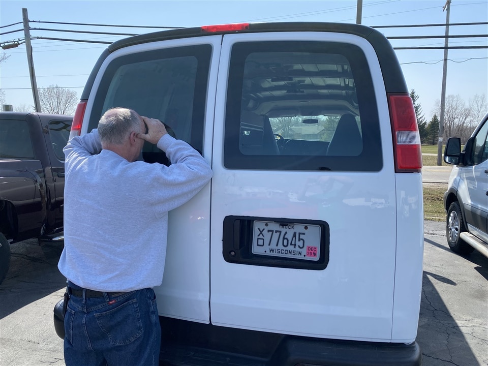
My father came down from Michigan to my house in Wisconsin (Milwaukee area) to find the ideal van. He was here for about a week then returned to Michigan. We had found a van, and I helped finish the sale process and picked up the van. I told him I’d help “hang up a light or two” and arrange to get the van back to him once it was ready. He didn’t know that I had schemed with my siblings to do a full-blown build-out. Once the van was complete, I flew him down and presented his gift on what happened to be Father’s Day this spring.
I'll talk a lot about the Jackery 1500 that we used for the main power station, so be sure to check out this link for more info about it.
What is a Camper Van?
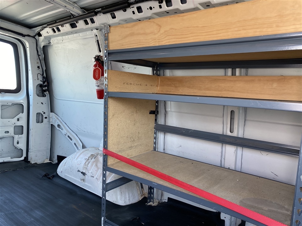
A camper van is essentially a small RV. It is self-contained and has all the things required to live - sleeping accommodations, bathroom, kitchen, living area. I added solar panels and a Jackery power center. From the outside of the van, this particular van was designed to be stealth, so if you walk by it in a parking lot, you wouldn’t suspect that someone was living inside it. It just looks like a normal Chevy Express cargo van. Having an RV is nice and spacious, but harder to take through drive-throughs and more obvious if you park it overnight at a Wal-Mart or hotel parking lot. For this build, the base machine was a Chevy Express cargo van. We found one that had been used previously by a handy-man. It had a utility shelf stuck in the back for holding gear.
Major sections of the build
I’ll break this down into a few major sections and talk about each one individually. I’ll cover electrical last to make everyone wait - but there was some pretty interesting things that happened in this area.
- Pre-build planning
- Insulation, walls, floors
- Sleeping area
- Plumbing
- Sink, water tank, pressure pump, drain, toilet
- Main counter & shelving
- Electrical
- Solar panels, charge controller, battery, power inverter + 12V system
- Lessons learned
Here is the base van from when we bought it.
| {gallery}Base van |
|---|
|
First looks: My dad taking his first peek at the van when we went to the car lot |
|
Interior: Free shelving unit with the purchase of one van! |
|
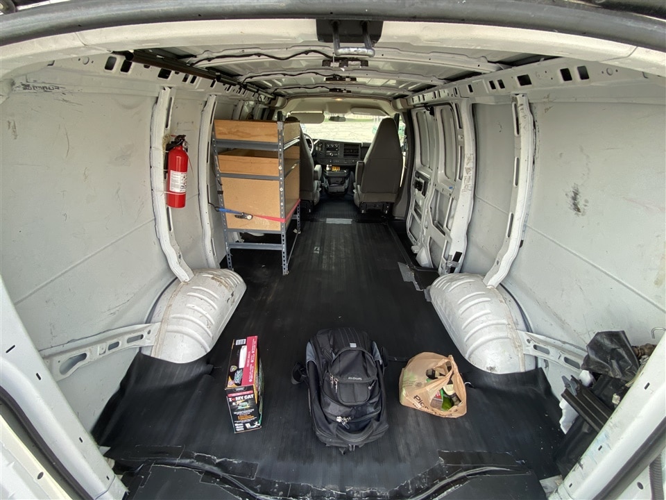
Rear area: Ready for a makeover! |
Pre-build planning
 This was designed to be a mobile house while providing room for music gear. I spent a lot of time talking with my dad to decide on the general layout, required accommodations, and how much gear would be included. I started in Fusion360 and got a model of a Chevy Express van. Then I started dropping in the different components. I had my dad measure all of his music gear, and I modeled it all so I could figure out how much space it would take up. I sent him different renderings and asked for feedback via WhatsApp. These renderings are fun to look back at once the build is complete
 .
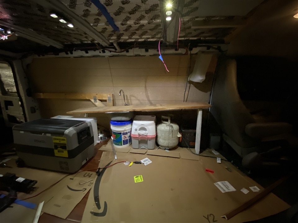
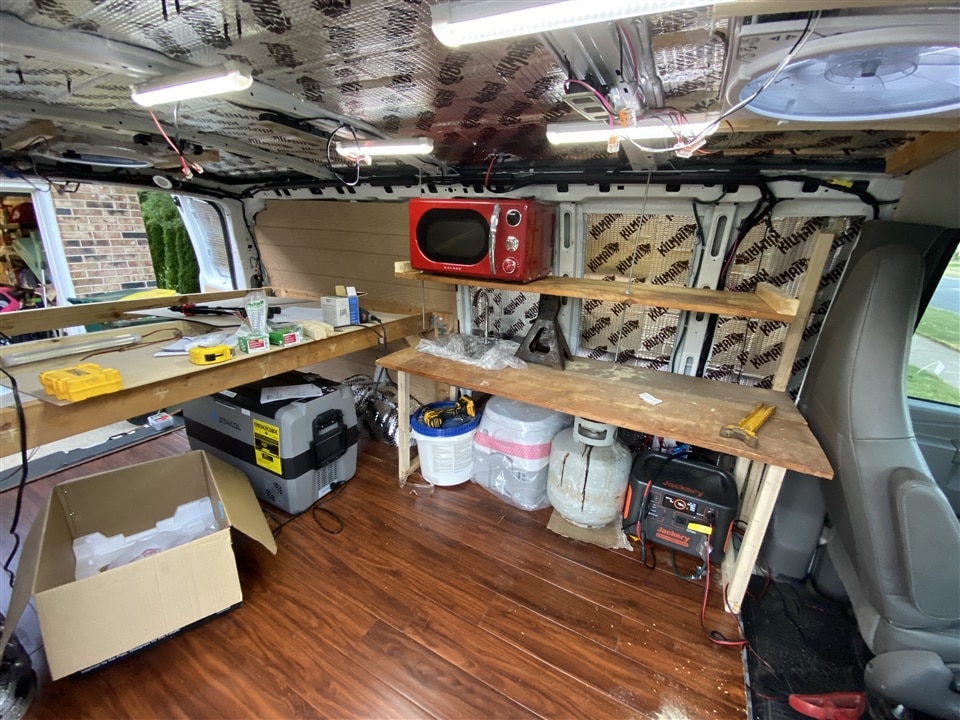
We had decided to put the main electrical behind the driver’s seat. That section of the van became its nerve center and housed a lot of the plumbing as well. It held the sink, grey water tank, toilet, Jackery power center (battery, inverter, etc), and room for a propane tank. Above the main counter was a shelf that held the microwave. The sleeping area was on a "loft" inside the rear section, with a "trunk" below it that can be closed off from the interior. I would pre-wire a bunch of lighting - bright in the main area and soft in the sleeping area. There would also be plenty of USB outlets and 12V outlets available to keep all the gadgets charged. The front of the van (the two driver seats) would mostly be un-altered, but I did get a 'swivel-seat' adapter for the passenger side so it could be like a lay-z-boy in the van.
My dad sent me the picture on the left showing his preferred layout. I did my best to follow this and came pretty close. I only ended up with a shelf instead of cupboards since I ran out of time, but once the microwave was installed there wasn't room for much cupboards anyways. I laughed because most of what he put down was "music" and "music storage".
| {gallery}Planning |
|---|
|
General layout: This became the general layout of the interior. |
|
Roof plan: MaxxAir fan and solar panels. I ended up with two fans and two panels; with room for a third panel later. |
|
Sleeping cross-ways: I looked at sleeping crossways in the back, but if any gear is stored on the loft, it created a barrier. |
Insulation, Walls, and Floors
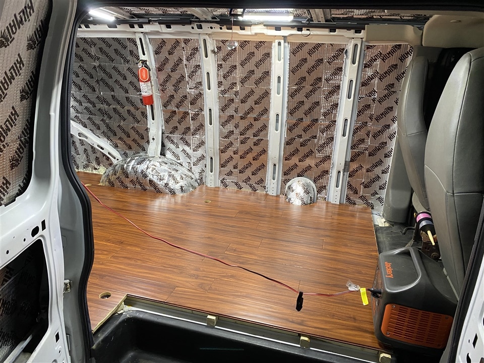
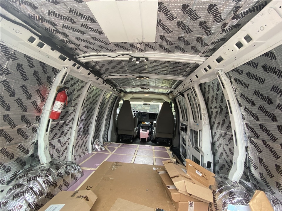
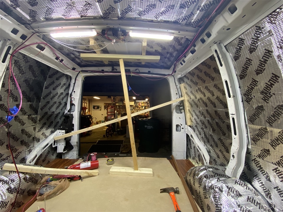
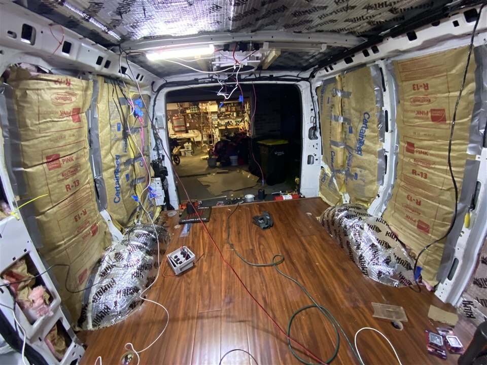
To start out, the base van was stripped - rubber matt on the floor was pulled out along with the shelving. I pulled out everything in the back of the van and swept the bare metal. I started by installing some sound deadener (the Amazon brand version of Dynamat) and rolled it out over the whole inside back end of the van. This makes a big difference in how loud it is inside the van when driving down the road and keeps it quieter inside. The next step was insulation for the walls and ceiling. I re-used fiberglass insulation that I had left over from my house when I insulated the garage. I used a lot of duct tape to secure the insulation since I couldn’t staple it to the steel ribs on the inside of the van.
For wall material, I used light colored woodgrain wall paneling from the hardware store. I was going back and forth on how to make the walls - this paneling had very little structural rigidity; but the alternative would have been to use something like plywood. If I had used plywood then I could easily mount things to the walls anywhere I choose; but it would have been very difficult to attach and shape. The interior of the van basically doesn’t have any straight lines or 90 degree angles. The floor was pretty flat, but the walls are curved outward and the ceiling tapers - tallest in the middle of the van and shortest by the back doors; while also being curved. By using the wall paneling, I was able to easily bend it to fit and it could be trimmed very easily. It was also very inexpensive.
To make each section of wall, I started with cardboard and made a template. Since the panels were so large, I had to tape together a bunch of smaller pieces of cardboard to make the big enough for the 4’x8’ panel sections. The cardboard template was made, then I transferred the shape over to the paneling and cut it out. To attach these to the interior ribs of the van I used self-tapping sheet metal screws. Finalizing all the wall panels was actually spread out over the course of the entire build since I had a lot of electrical running through the walls and had to install & remove them multiple times.
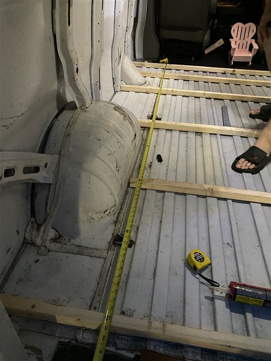
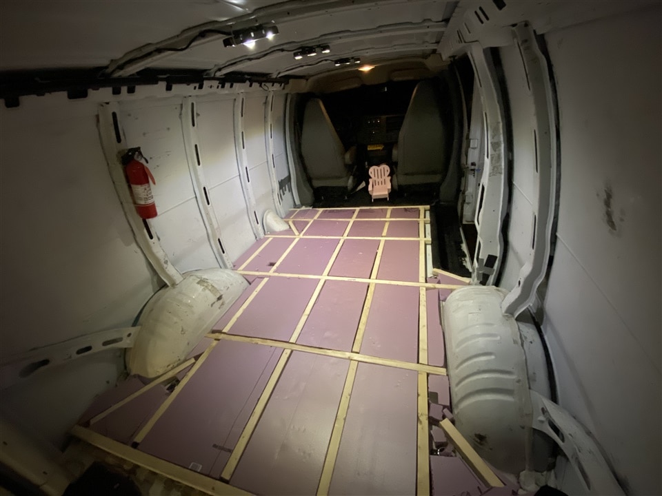
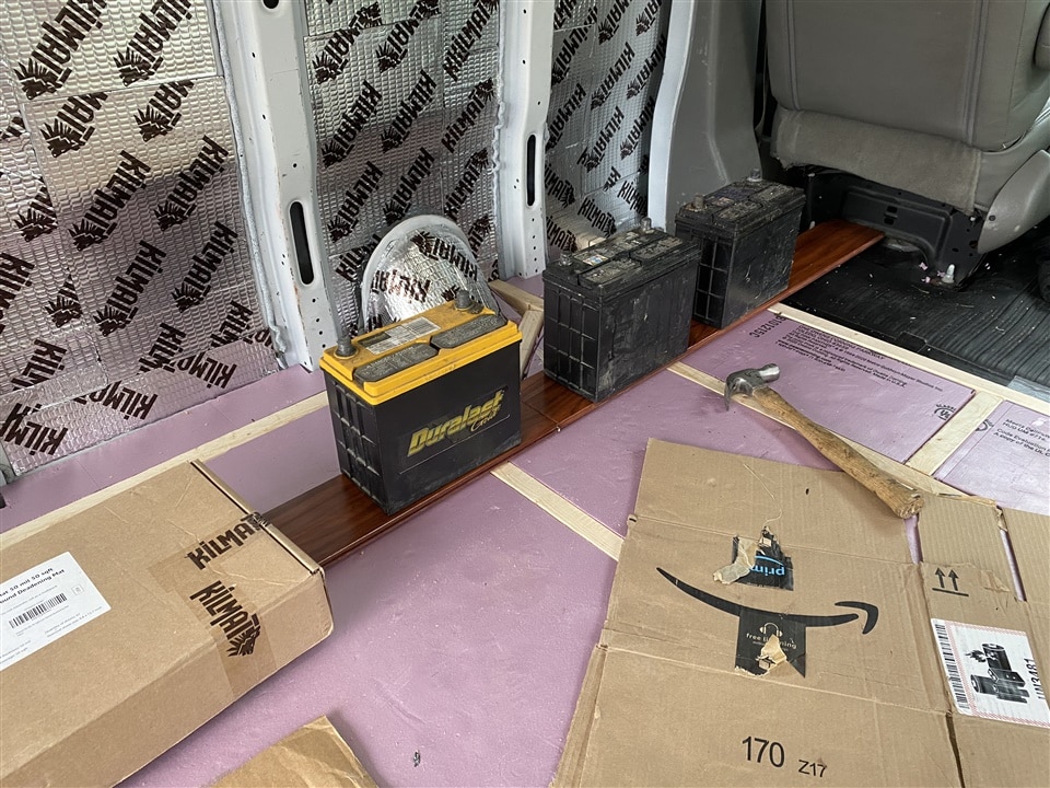
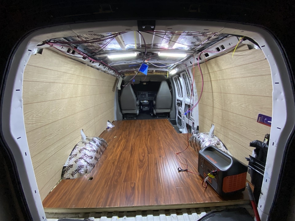
For the flooring, I started by cutting out a frame of 2x2 wood and using construction adhesive to glue it down to the steel floor. I then used foam plank and cut it out to fit inside each section for insulation. On top of that, I used some leftover hardwood flooring from my house and installed a beautiful floor - pretty funny to see inside of a van . This was also glued in place.
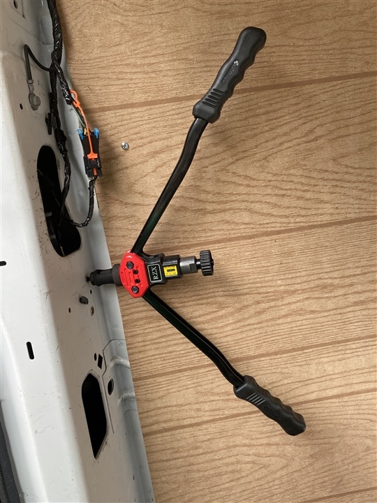
As the walls were built up and installed, I picked up a Riv-Nut tool and planned in all the required attachment points for the main counter, sleeping platform, and other hardware. This means that all the big components of the build were securely bolted to the structure of the van, and not just held in with bungee cords or sheet metal screws. It took some extra planning to get the riv-nuts installed before the walls, and leave a hole in the right spot to add things in later.
| {gallery} Flooring |
|---|
|
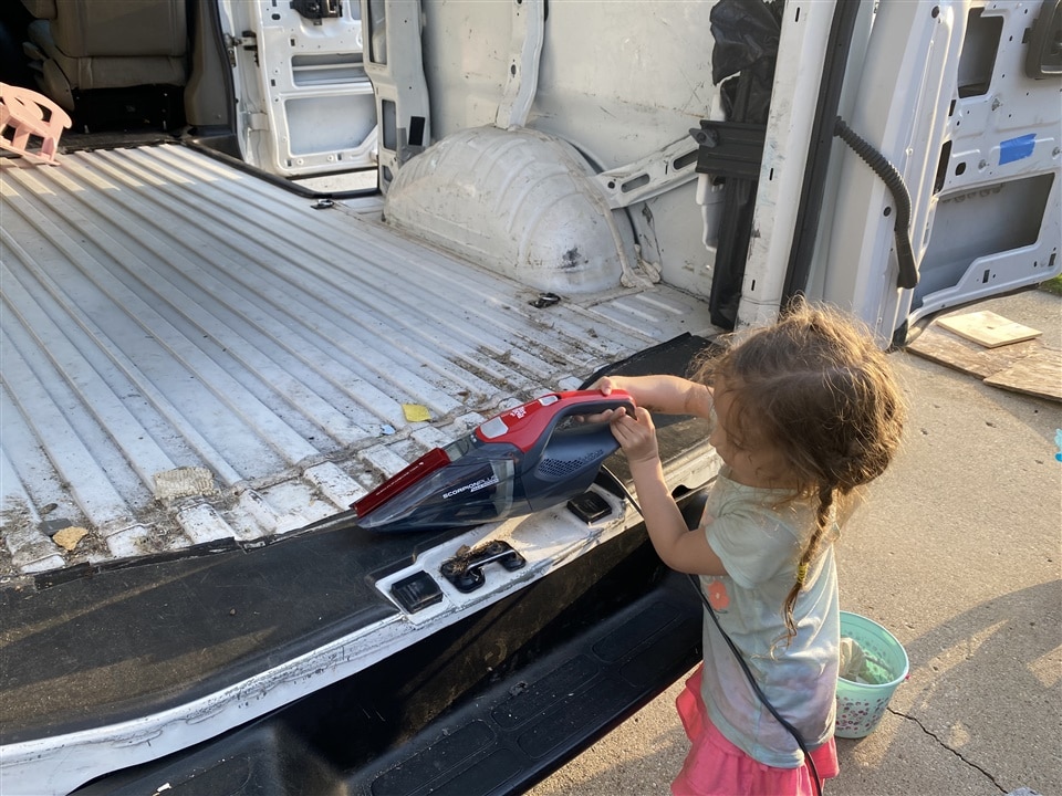
Prepping the floor: The first step was pulling out the rubber matt and cleaning the floor. I got help for this part |
|
Framing the floor: I glued down 2x2 lumber with construction adhesive in a grid. |
|
Insulating the floor: I used foam plank to insulate the floors at least a little bit. |
|
Hardwood floor: The hardwood was then glued down. I'm using some fancy electrical components here |
|
Hardwood complete: The new view! |
|
Hardwood complete: A look in the back. Later on I capped the edges of the flooring. |
Walls
Images showing building the walls up.
| {gallery}The Wall |
|---|
|
Sound matt: Sound matting went up first, right against the van walls. This alone made the van much quieter. |
|
Interior bracing: I glued some 2x2 boards in various spots of the van so that I could secure walls to them later on in the build. Turns out gluing them to the sound matte was a bad idea... This image shows using other boards to hold them in place while the glue dries. |
|
Cardboard Templates: Just a few of the many cardboard templates that I made to help cut out the wall panels. |
|
Insulation: Next the insulation went up; held securely with duct tape. The ceiling was done also, but not pictured here. |
|
Walls are in: The walls are shown here, back installed in the van. The ceiling would be installed later; and ALL of these had to go in and out a few more times in the build to get the electrical harness finalized. |
Sleeping Area (aka the "loft")
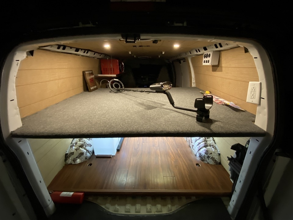
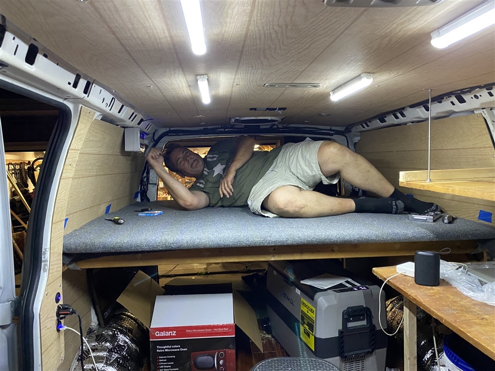 I ultimately decided on building a platform loft in the back of the van to allow sleeping. My dad requested easy access to get out the back door from the sleeping area in the case of emergencies so I made sure that there was room. He and I had spent some time deciding on whether to sleep crossways or long way on the platform. Ultimately it was decided to sleep the long way, and leave room along the other side of the loft for gear or drawers. I made a platform with 2x4 wood that was bolted in to the ribs of the van with 1/4-20 riv-nuts.
On top of the platform, I used two pieces of plywood cut to match the curvature of the van side (which taper to be much smaller at the back). On top of that, I used up more house materials that I had laying around - carpet padding and outdoor carpet. The result was a beautiful soft loft that was perfect for sleeping on. One downside is that the bed isn’t tall enough to sit up in which is kind of a big deal. I was able to talk to someone who has been doing the Van Life thing for a few years and he warned me about this. I did it knowingly because the height of the platform was required to fit all the music gear and water storage tank underneath. One thing that I ran out of time for was adding a small extension for his feet - they actually hang off the edge of the platform unless he curls up a little bit.
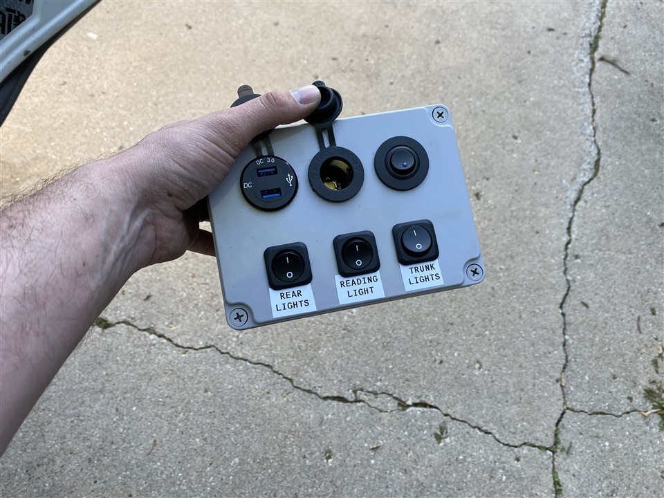
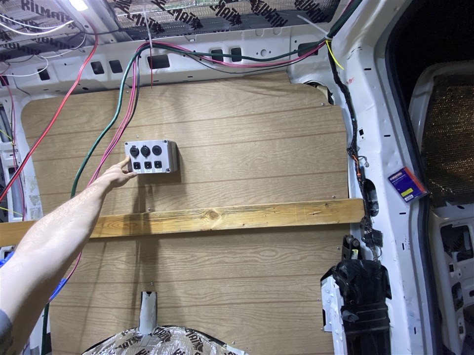
I created a rear electrical control panel in the sleeping area. There are four small reading lights in the ceiling that I added, plus a 12V outlet and two USB outlets. I bolted this to the van structure right next to where he will be sleeping so he had an easy place to plug stuff in like his phone and his CPAP.
The image here shows my neighbor testing the bed. It is a bit cramped to get in, but quite comfortable after that. You can see the switches and outlets by his right hand on the wall.
| {gallery}Building the loft |
|---|
|
Where to sleep: My dad shows his preferred sleeping location when we were buying the van |
|
Partial frame: building up a partial frame for the loft. This will get bolted to the steel ribs when installed. You can see a bracket on the left for this. |
|
Riv Nut tool: Installing the first riv-nut. I highly recommend this tool to anyone who works with sheet metal. This can install threads into sheet metal just like a rivet. |
|
Bed frame almost done: Starting to install the decking; 3/4" plywood. |
|
Made a mistake: This is when I realized that I measured wrong and cut the decking about 2" too short, ruining the plywood. I had to get one more sheet for $70. Note the awesome E14 Community shirt i've got on |
Plumbing
How do YOU poop in a van??? This is a very common question that people get. I spent a lot of time considering the options. A lot of people use a “Luggable Loo” which is basically a toilet seat on top of a 5-gallon bucket. Ultimately I picked up a Dometic portable toilet. This is a self-contained port-a-potty. It is a pretty small package - only about 1.5f in each dimension. It has a fresh-water tank on the top section surrounding a normal toilet seat. There is a sealed-off section on the bottom half for the black water/waste. You use it pretty much like a normal toilet and you can even pump up the water pressure and give a legitimate flush when you’re done. Since the bottom half can seal off, you won’t be left smelling anything. The two halves separate and the lower ‘cartridge’ can be carried into a rest stop and poured down a normal toilet.
I created a spot under the main counter to store this and used some bungees to lock it in. There are 2x2 braces built into the floor to keep it from sliding around.
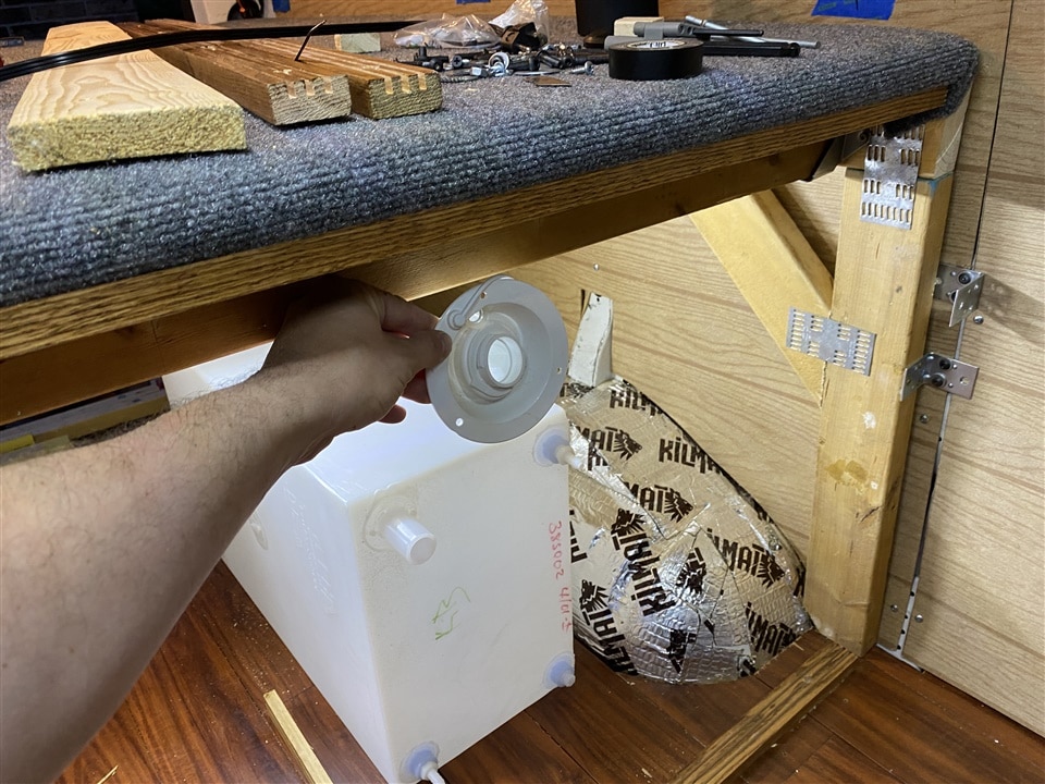
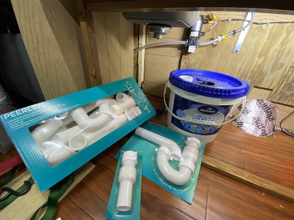
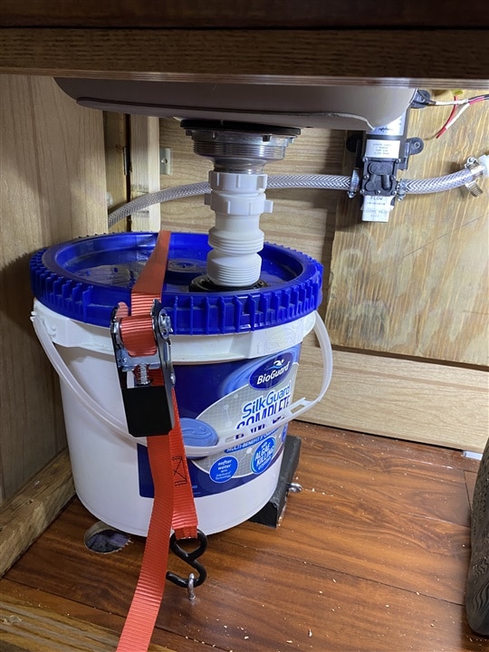
For the main water system, I started with a 16-gallon fresh water tank. I used 1/4-20 threaded rod and some steel angle to bolt it to the floor in the ‘trunk’ area. There is a 12v pressure-activated water pump in-line leading up to the small sink. When the pump is powered, it only runs when the faucet is opened. This means that you can use the sink just like you would at your home. Just turn the faucet on and water comes out. The drain system (grey water tank) was a bit trickier to put together. A 5-gallon bucket would have been too tall to fit under the sink. I spent a lot of time walking up and down the aisles at Home Depot to find /anything/ that had a smaller bucket that I could use. Ultimately my friend brought over an old bucket that used to have pool shock. It was about 2/3 the height of a 5-gallon bucket and about the same size around. I found a rubber gasket to fit the sink drain through the bucket lid and used some tie-down straps to secure it underneath the sink. I found a flex-coupler to go between the sink and the bucket.
To empty the grey-water tank, just raise the flex coupler to get the drain out of the bucket, and remove the tie-down straps and the bucket can come out. In the field, it could also be poured into the upper section of the Sami-potty toilet and used there.
The plumbing was pretty much the last section of the van that I completed, and was done mostly between midnight and 3 am on the days leading up to the final reveal and delivery. I was having all sorts of difficulty finding the right plumbing fittings between the flexible tubing and weird flex couplings and had to go to WalMart and buy all of the multi-packs of plumbing fittings, then spent a bunch of time trying all the different fittings.
| {gallery}My Gallery Title |
|---|
|
Water tank and filler: This is where the tank and filler neck got mounted. I kept the filler neck inside the van rather than doing a cut-through and filling from the outside of the van. |
|
WTF drain: I spent a lot of time finding the right size bucket and fittings. There's basically no standard plumbing parts in this entire thing... The pressure pump and tubing can be seen in the background. |
|
Job done: Used some tie-downs to secure the drain. The flex line can pull up to let the bucket come out for disposal. |
|
Sink and toilet: Sink installed above. Still working on the drain below. The toilet from Dometic is shown here in its approximate final location. |
Main counter & shelf
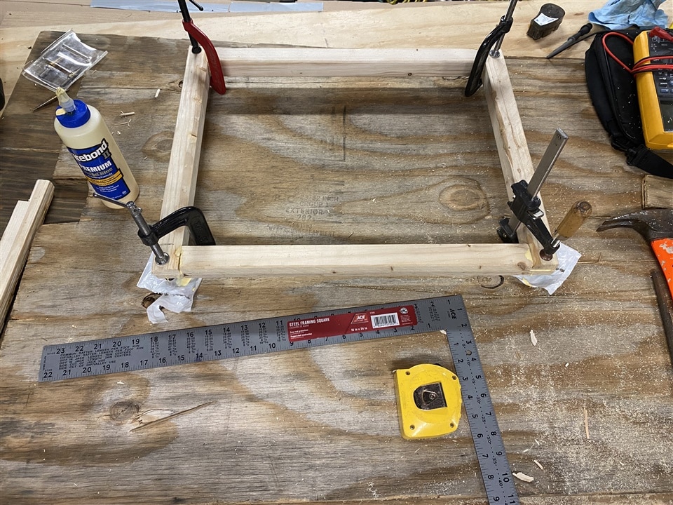
I had to build up a counter for the sink and food prep area, and ended up using it to hide all the 'utilities' underneath. I did a simple frame from 2x2, and the countertop was made from some old wood I had in my garage. I sanded and stained it once complete. I had originally walked around the local "re-store" (where a lot of construction workers bring in gently used appliances, counters, doors, windows, furniture, etc, to be used again. I had my eyes set on a nice used kitchen counter with cabinets, but would have had to rework basically the entire thing to make it fit in the van. It seemed easier to just make my own in the end.
I also created sliding doors from some paneling and 1x2 wood strips with grooves cut in them. The panel doors slide shut to hide all the utilities and close off the trunk area. I used some extra LED lights to provide under-cabinet lighting for the shelf, utility area, and trunk.
| {gallery}Main Counter |
|---|
|
Early Mockup: An early mockup of the main counter. Sink can be seen hiding in there somewhere... The Jackery barely fit, and actually stuck out a little towards the drivers seat. |
|
Gluing up the frame: The two ends pieces were glued up like shown. |
|
Counter almost done: The counter was almost done in this image. For the microwave shelf, I used RivNuts and ran 1/4-20 threaded rod into the ceiling ribs of the van to hang it. |
|
Sanding: My Neighbor came over to help sand the table |
|
Pretty much finished: The counter is stained and installed. The doors can be see below the loft which were similar to do the doors on the utility area. Note the fancy under-cabinet lighting and the bright lighting in the utility area. |
Electrical!
The part you’ve all been waiting for! I’ll break this down into a few sections.
Solar
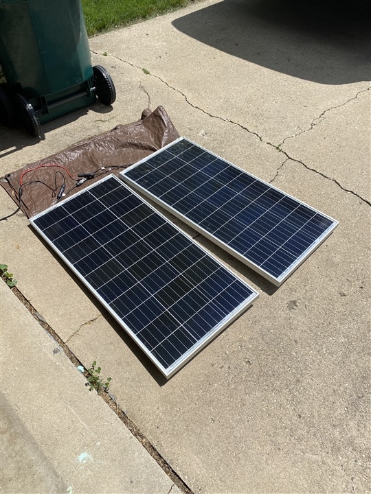
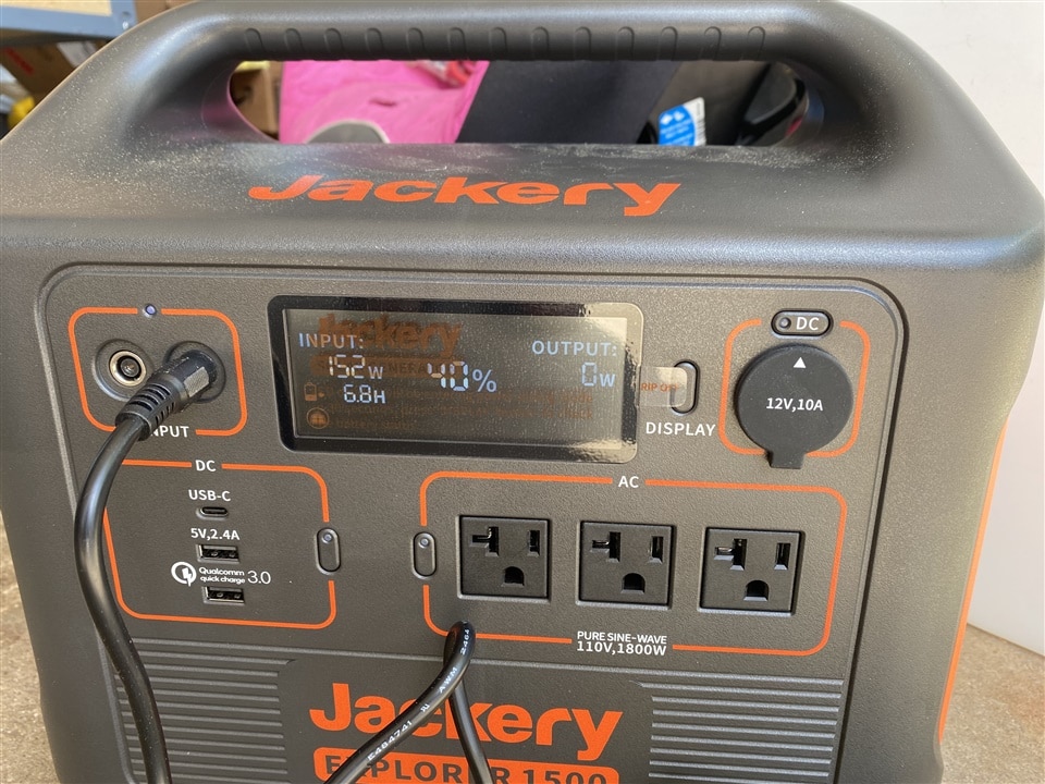
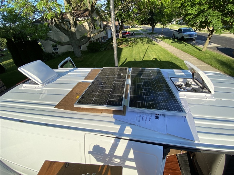
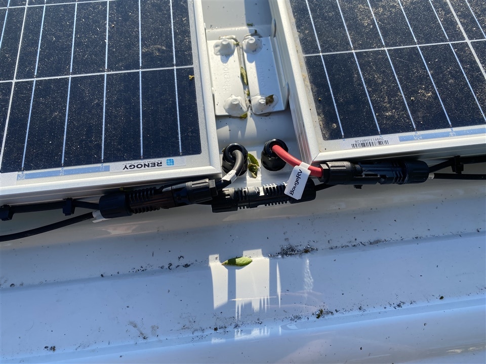
The electrical starts with two Renogy 100-watt solar panels. I went on top of the van and bolted and waterproofed the two panels securely. I planned ahead and left room for one additional panel if needed. The panels were wired in series and the wires go through cable glands to get inside the van. They plug into a Jackery 1500 unit which is the central piece of the electrical system. This serves as a solar charge controller, battery, 12V power source, and 115V AC inverter (pure sine). The 1500 model Jackery can source 1800 watts and has about 1500 WH capacity battery. I actually used this to power my radial saw and basically all the tools I used during construction of the van.
 If you aren't familiar with solar panel wiring, they typically use an "MC4" connector. The MC4 is weather tight and has male/female ends which are both shielded so that it is unlikely to accidentally short them on anything. Solar panels cannot be "turned off" so they should always be considered as "hot" or "active". Solar panels also can only make DC electricity. Depending on a specific application, they can either keep the power in DC and charge a battery bank (which conveniently is also DC; therefore efficient), or the power can go through an inverter to create Mains-level voltages. If you were to get something like a "whole house battery" that also stores energy in DC, but it must be flipped back to AC to be fed into your house. In my case, I was doing a 12V system for a van, so the panels fed into the Jackery charge controller which keeps a DC Li-Ion battery charged up. The Jackery was also very convenient for this application since it served as a solar charge controller, battery, 12V power source, and a mains inverter; all in one simple package. Normally I would have spec'd out each component individually and built the system from components, but I couldn't see my dad troubleshooting a complex system at midnight on the other side of the country. (side note - another common connector is the Anderson Power Pole which are polarized square plastic connectors).c
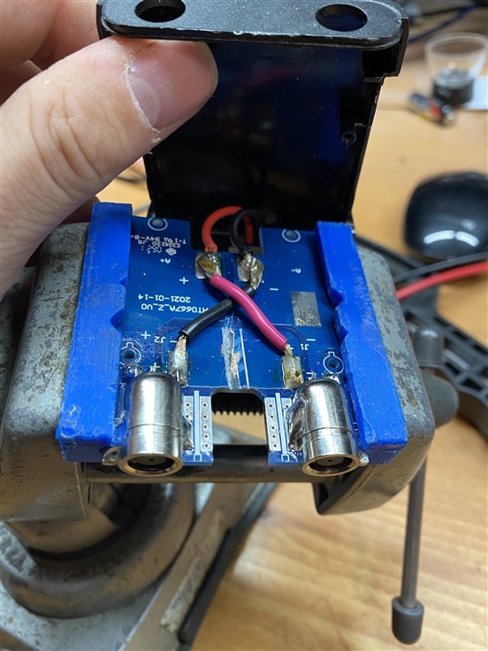
Since I was using Renogy brand panels with the Jackery, I had to modify the Jackery solar panel connector. The panel wiring used the MC4 connectors on one end, and DC8, 8mm plug on the other. The Jackery appeared to use a DC8 input connector for solar panels, so I picked up a few different MC4 to 8mm adapters. But none of them worked... Apparantly, the Jackery 1500 and larger models use a proprietary connector that only looks like a DC8. They did, however provide an adapter which has 2x DC8 inputs and one "Jackery" side output connector. Buuuuut it didn't work either with my single string of panels. They refer to this as a "parallel" connector, but after opening it up, it is just a series connector. So I would have needed to plug in two strings for this to work. I ended up cutitng the tracks and added new jumpers to make it into more of a "Y" connector. I added some labels to it after reclosing so that anyone looking at it later would know that it was modified.
The image on the left here shows the result of the modification. The large trace was cut that bridges the two solar panel inputs, and I soldered jumpers over to the outputs.
Sizing the Solar system
My dad was talking about the Jackery 500 but we splurged a little and got the 1500. There is a good exercise here in sizing a solar panel system - I added up all the devices that he would be using:
- 12V fridge (largest load)
- Microwave
- CPAP machine during night
- 2x ventilation fans
- phone chargers and power outlets
- interior lighting
The 1500 was about the only one that could sustain the fridge for an extended period. It turned out that 200 Watts of solar panels can only really charge the battery enough on a really sunny day (in wisconsin). If he is in Florida, he’ll be in better shape (better angle to the sun and more solar insolation. I found during the build that a cloudy day really took a hit on the system but it could survive if the following day was sunny.
Adding a microwave is a bit controversial in the Van Life world. They suck up a lot of power and require 110V which is extra lossy. At the same time there are other ways to heat up food like a propane stove. I added a microwave on this build since my dad doesn’t really cook that much but is well versed in using a microwave .
| {gallery}Solar panels |
|---|
|
Testing: Solar panels laid out on the ground testing |
|
Jackery: Jackery getting power from the sun. Charging at 152 watts |
|
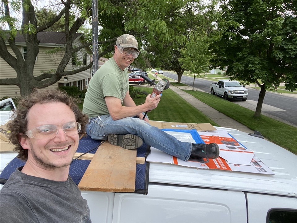
Point of no return: My friend Jeff and I installing the solar panels and cutting some very large holes in the roof of the van for the vent fan. |
|
Almost there: Both fans installed and one panel. |
|
Power pass-through: I used some cable glands to pass power down through the roof. No leaks yet! Yeah, I know that these connectors should ideally be placed horizontally but I didn't have that option here. The MC4 connectors can be seen here. |
|
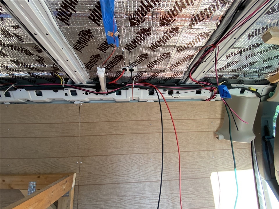
Interior power Entry: This is where the main power comes in and joins the soon-to-be-wrapped electrical harness. |
Fridge
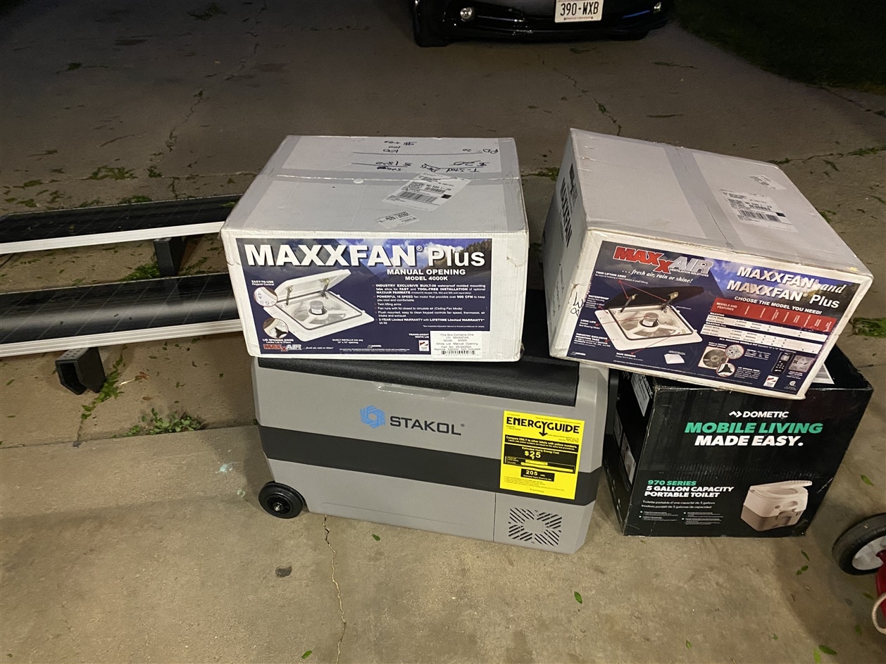 For the fridge, there are basically two general categories. Electric and Compressor based. The Electric uses Peltier elements to generate a temperature differential. I have a tiny car fridge that has one and it takes about a week to cool down a 12oz beverage. The compressor based version is largely similar to what people have in the homes. It uses a refrigerant and a compressor along with two radiators and can easily generate a large thermal difference. Unfortunately they are much more expensive than the electric versions, but are ultimately better. I got a recommendation for a “Costway” brand 12V fridge (it came with "Stakol" label as shown in this picture). This model has a central divider to create a fridge section and a freezer section. The divider can be removed to create one large area which can be either a fridge or a freezer. I decided to place the fridge between the front two seats of the van since it is mostly out of the way from the ‘living area’. This has the general size and shape of a traditional cooler. The fridge can be seen as the greyish cooler looking thing in the image at the left.
Avoiding use of 110V in the van...
For his CPAP, I snuck a peek at his when he was visiting. It has a very large 110V medical-grade power brick that supplies 24V DC to the device via a weird plug. Running the CPAP from mains would be really lossy in the van (12V DC -->> 110V AC Inverter --> 24V DC) I started looking around. I found a 12V mobile adapter for his CPAP that used a standard 12V automotive outlet. Inside is just a boost converter that is built up to medical specs. So I picked this up and was sure to include a 12V outlet next to the sleeping area. I also found a similar 12v adapter for his electric shaver which uses 15VDC. The shaver would only run for a few minutes per day, but if I could just get a DC supply it would be easier.
Vent Fans
While up on the roof doing the solar panels, I also installed two MaxxAir ventilation fans - one in front and one in back above the sleeping area. This was also a tip from the person that I talked to - two fans instead of one can create a cross-flow of air through the vehicle. I installed one near the front of the van and the second in the rear, right above the sleeping area. This required going on top of the van and cutting a large 14” square hole in the sheet metal. Kind of a ‘no going back’ installation. These fans are reversible and have about 8 speeds in each direction. They are almost silent at the lower speeds which is great for stealth camping in a parking lot.
Power Points
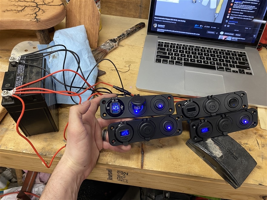 Phone chargers - For this I picked up a few 12V outlet sets on Amazon. Above the main counter, I installed two of them - They have an on/off switch, a 12V outlet, and two USB outlets. So there are four USBs at the main counter and a 12v outlet for the fridge. Behind the side door of the van, I put in another set. The last set was installed by the sleeping area. So there should be plenty of locations to plug stuff in and lots of chargers. The on/off switches allow turning off the USB outlets to save power.
 For 110V power, there is a power strip plugged into the Jackery and mounted in the utility area (under the counter). I also ran an extension cord to the back of the van and installed a GFCI outlet right by the back door. So my father could just open the doors of the van and play an entire gig plugged into this outlet. I also explained to him how to avoid using 110V if at all possible.
These two images show the stack of outlets I used, and testing them by pulling 4 amps @ 5V - EEEK!
I didn't use the rectangle faceplates that these shipped with, I just pulled the components out and re-mounted them around the van. I made sure there was plenty of outlets so he wouldn't have to scrounge or resort to using 110v devices.
Interior lighting - with another electrical hack:)
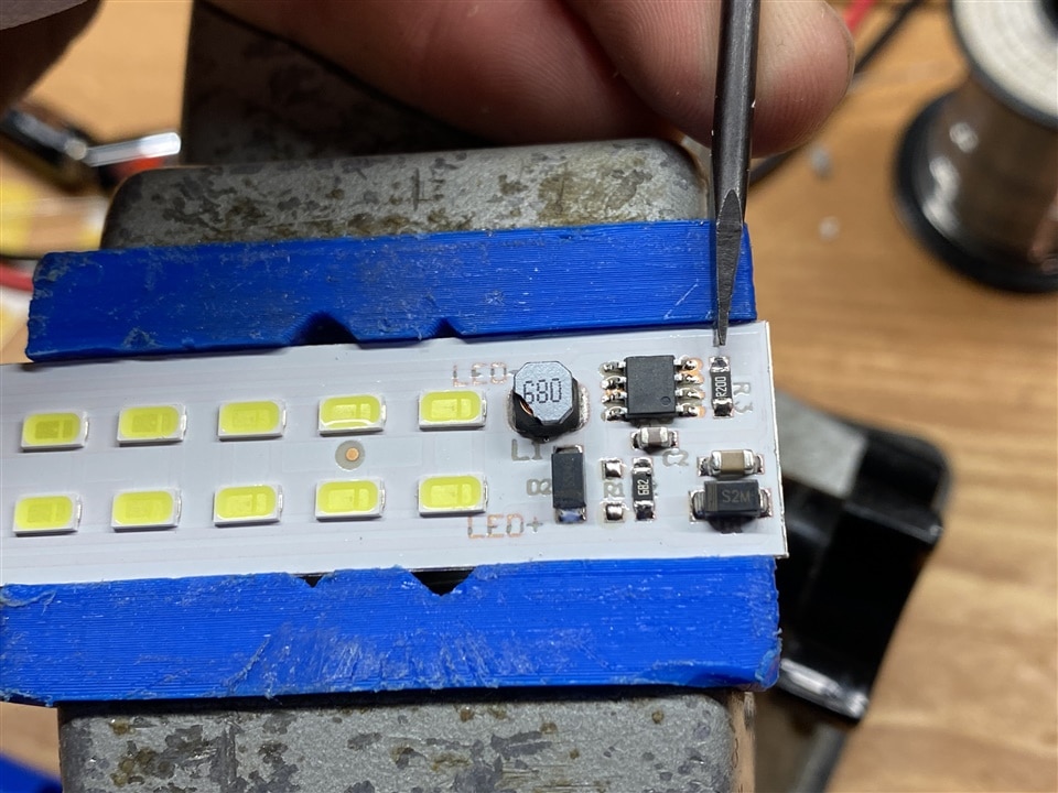
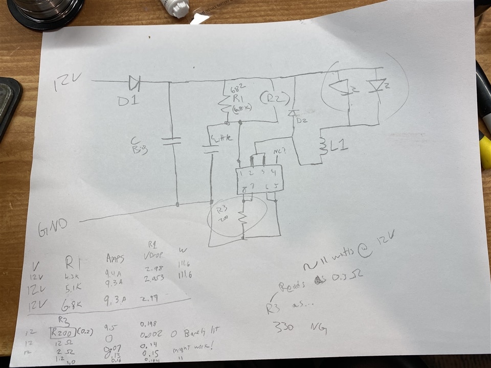
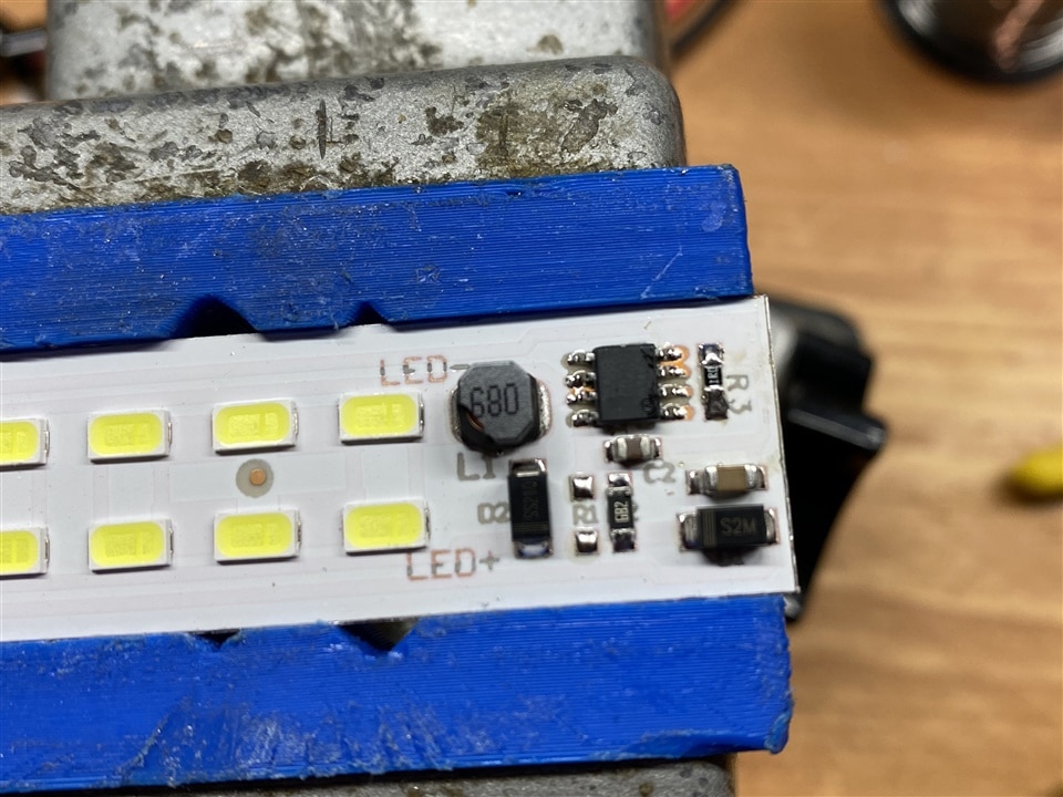
I picked up a stack of 12V LED lights for the van from Amazon. I must not have been paying too much attention since I got twice the number of lights that I was thinking - because they were two-packs. But no bother, I just used them in more places. There was a fun hack here with the lights. I’ve watched enough Big Clive to know that OEMs tend to blast LEDs with as much current as they’ll suffer to make the light super bright. This wastes a lot of energy and really isn’t needed. I took the lights apart and found the feedback resistor R3 and swapped it for a different value (settled at a 1 Ohm) and was able to get them to use much much less power but still be plenty bright. I installed four lights in the main area of the van; then one under the counter in the utility area, and two inside the ‘trunk.’ The trunk lights allow loading gear at 2 am in the dark after a gig. The one in the utility area was just done quickly without much thought since I had an extra one, but was super useful when working down there. I also posted this hack in the comments of the Amazon listing
| {gallery}Lighting Hack |
|---|
|
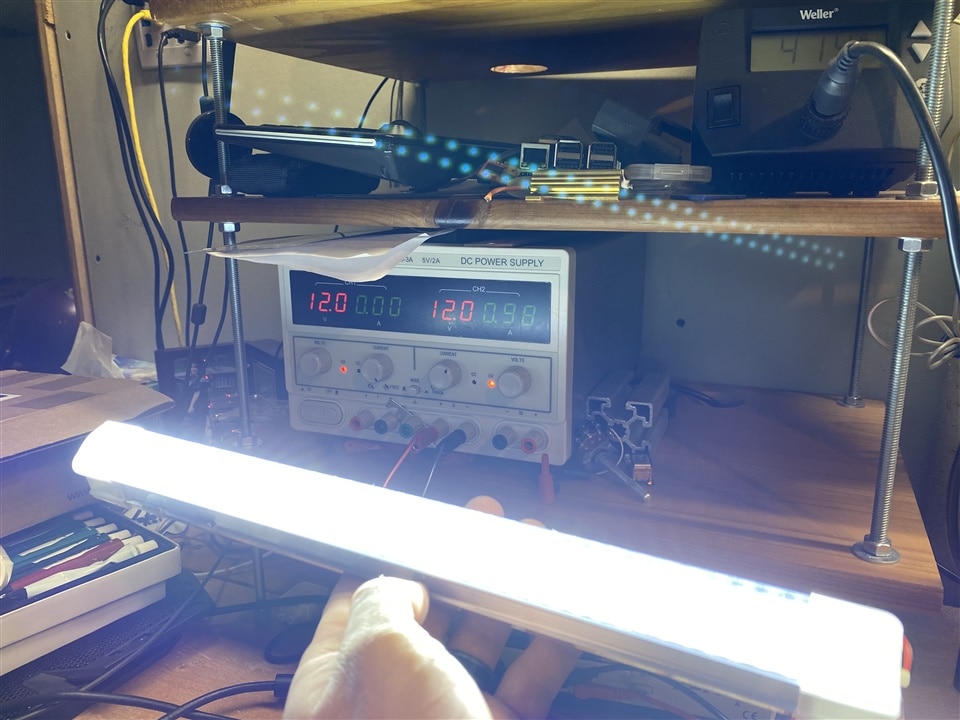
Before: Before the hack, the light consumed about 1 amp @ 12v. |
|
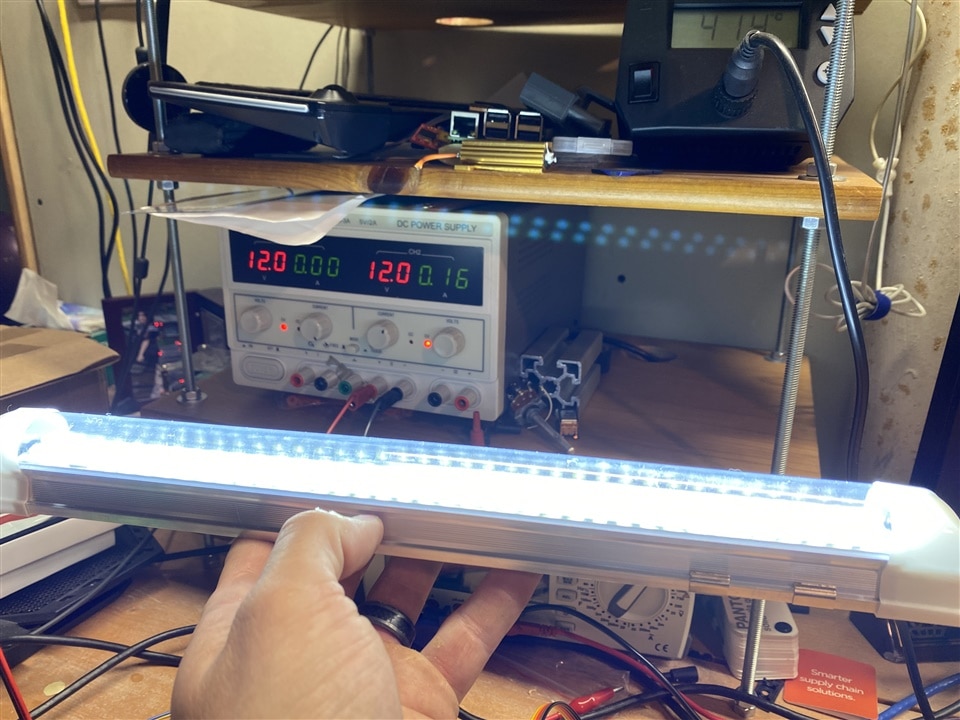
After: After changing out the sense resistor, the light used only about 160 mA @ 12V. An 84% reduction! |
|
Sense Resistor: R3 is what I had to swap out. |
|
Reverse Engineered: My scratch pad showing the schematic I reverse engineered. I though at first that R1 was the sense, but was wrong. R3 was what needed to be changed. |
|
After surgery: The new R3 in place. |
The hack resulted in going from 12v/1 amp to 12v/0.16 amps, so around 1/8 (ish) of the original power consumption. See photos below of my Tenma power supply (from an earlier E14 prize package )
Above the sleeping area, I installed four small round, warm LED lights. They are switched on and off from the control panel in the sleeping area. As with the rest of the electrical, the wires were all harnessed together and secured inside the walls; so that there is no exposed wires.
Main 12v harness and power distribution
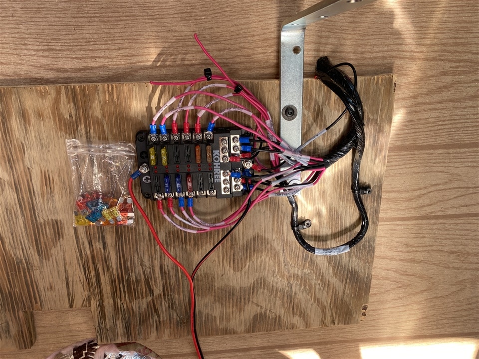
As the van build progressed, I had started pulling wire around from the central power location under the counter out to each device. I used 16Ga copper red and also ran a ground for each device. The fuse panel that I got had convient landing locations for a ground on each circuit, so it made things easy. I also didn't have to worry about grounding each device at its location individually. (Side note - I've wired a few classic cars previously. Most steel-bodied cars DO just run 12V and let the car body act as the ground since the battery is tied to it (exception: positive ground cars). The more unique use case and probably one reason that my fuse panel was designed as such would be for fiberglass cars that cannot use the car body as a ground.) The fuse panel was bolted under the counter to the van wall. It got 12V from the Jackery main DC output and I tied the ground in common with the van ground. For the AC output from the Jackery, I left the ground floating; but did use a GFCI outlet.
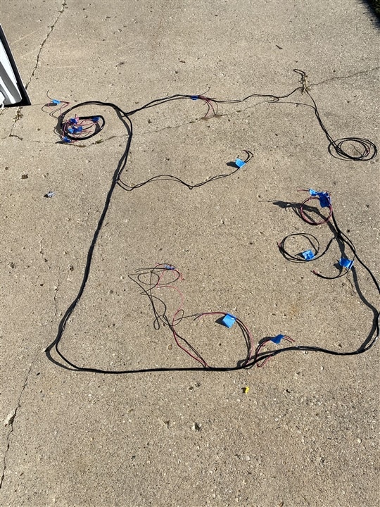
Once I had all the devices in their final locations - including the 8x ceiling lights that popped through the paneling - the harness was still just a mess of wires that was run through the van. I used zip-ties to hold it together at critical locations like Y's and pulled the entire harness out and laid it on the ground. Next, I wrapped the entire thing with a special 'harness loom tape' which is non-adhesive vinyl. This has the general appearance of electrical tape, or really it appears just like an OEM wiring harness in a car. The tape sticks to itself, but not the wires. I've even wrapped an entire loom before and had to extract a single wire after; and I could just grab it and slide it right out of the wrapped harness. If the tape is removed, there is no sticky residue.
| {gallery}Main electrical harness |
|---|
|
Wire Bundle: The main bundle of wires coming down from the ceiling, destined to land in the fuse panel (which can be seen in the background) |
|
Complete harness: The harness is laid out on the ground ready to be wrapped. |
|
Rear controls: Detail image showing the rear control panel. Light switches for the loft area and trunk, plus phone chargers and 12V outlet for the CPAP. |
|
Rear control mock-up: testing general location of rear control panel. The wiring harness is dangling from above. |
|
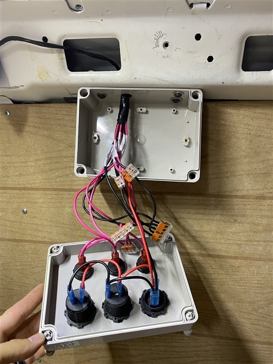
Rear controls wired: Did I mention that I LOVE Wago lever nuts? This took me about 3 minutes to completely wire in and I didn't have to huff any solder fumes. I had some left over from the Build Inside the Box challenge. I used a wire grommet to pass the harness through the metal body of the van (hidden from view above the box). Also note the beautiful wire labels on the harness |
|
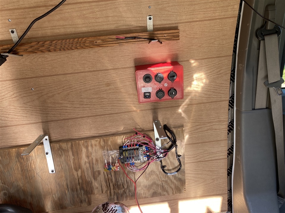
Front control box: The red box is the 'front' control box with USB, 12V outlets, a power switch for the well pump. The fuse panel is seen below. All wires ran behind the wall paneling. |
|
Fuse panel: Fuse panel mounted on wall, under cabinet (which was installed after this picture). All wires were beautifully labeled with my BMP21Plus Brady label maker that I got from E14 on a previous prize package. |
Lessons learned
If I had to do this over again, I certainly would have changed a few things. For starters, I would have chosen a van tall enough to stand up straight in. This one requires squatting at best and often kneeling on the hardwood when you're inside it. This also would have helped the situation with the loft area and not being able to sit up straight in bed. Adding one additional solar panel would have helped also. There are about a million little small things I'd do different, but this was my first van build project, so it was all a learning-as-I-go process. Even the plumbing was weird because I ordered a tank and couldn't even figure out from the listing what the connector size was in order to get the rest of the components to add the pressure pump and get into a faucet.
There were a bunch of small touches on this like the Reflectix window covers I put together which secure with magnets that I haven't written up. I thankful first to my father for raising me up and am glad to be able to give him something he's dreamed of (although he did buy the van, myself and my siblings chipped in about $5,000 to do all the upgrades; and I basically did all the work). He was only expecting some insulation and a few wires tucked in "for future use" and he got a van that he can literally just get in and go. I'm also thankful for my wife who again let me embark on a crazy project (anyone remember the Smart Range Hood?) and help me through it. Also my neighbor Sean for always being willing to help out and always showing up with Old Fashions in-hand.
| {gallery}Final Result |
|---|
|
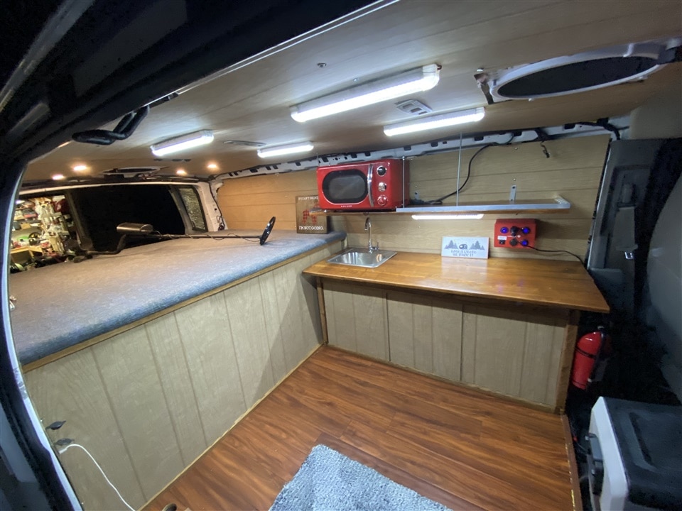
Main Area: The main area, sliding doors closed |
|
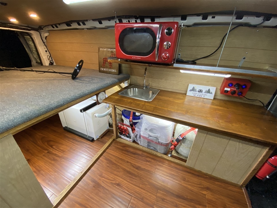
Main area: The main area with the doors opened. |
|
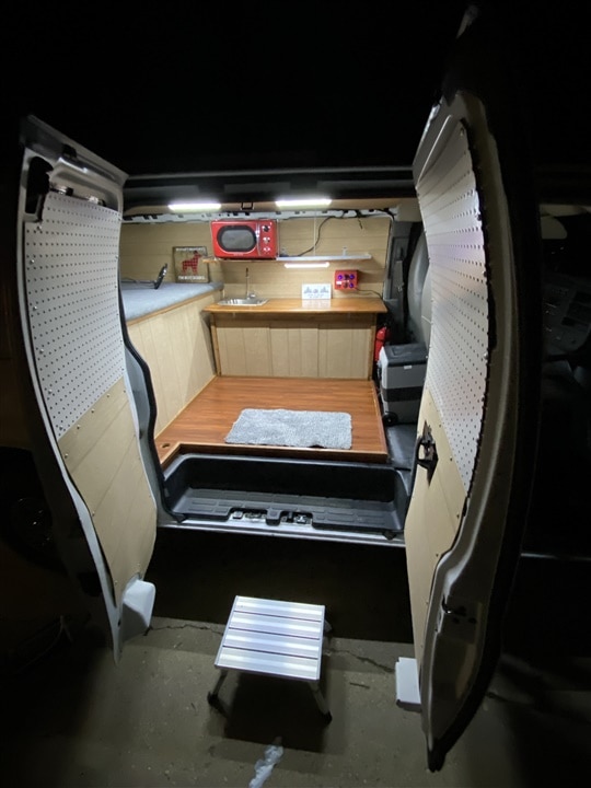
Side Entrance: With a nice little step to get in |
|
Finished loft: The loft area |
|
Trunk area: Water tank and enough storage for a bunch of music gear |
So far, he has loved the van.
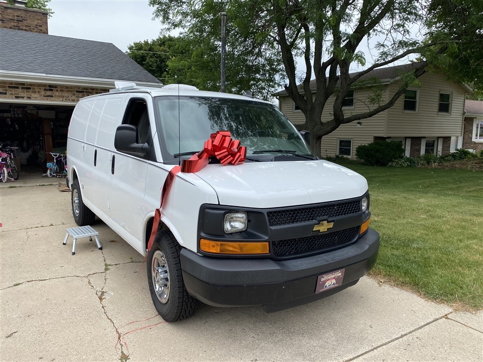
Here is a picture of us on Father's Day when I surprised him with his present. We even got a ridiculous bow for the car.

One final thanks to the E14 team who ended up supplying me (in one way or another) thinks like my Tenma Power Supply, Brady Label maker (BMP21+), and even the shirt I wear
This was a pretty big build and took over my spring this year (and even collided with Build Inside the Box challenge) but I was happy to do it and learned a ton.













Top Comments
-

aspork42
-
Cancel
-
Vote Up
+1
Vote Down
-
-
Sign in to reply
-
More
-
Cancel
-

balearicdynamics
in reply to aspork42
-
Cancel
-
Vote Up
0
Vote Down
-
-
Sign in to reply
-
More
-
Cancel
Comment-

balearicdynamics
in reply to aspork42
-
Cancel
-
Vote Up
0
Vote Down
-
-
Sign in to reply
-
More
-
Cancel
Children