


New! Improved! The Cat Lover's Flower pot is now:
- Bigger!
- IOT Enabled!
- Artistically presented!
- Actually has a plant in it!
See new information added at the bottom of this blog!
Background
My daughter asked for a 3D-printed flower pot. I don't know why or what, she did not say but a 3D-printed flower pot she shall get. Of course, it can't be just any old 3D-printed pot. She likes cats so let's do that. But surely it can be overcomplicated with electronics in some way? Maybe I can add exposed wires, sensors, pumps, and tubes!

Mechanical Design
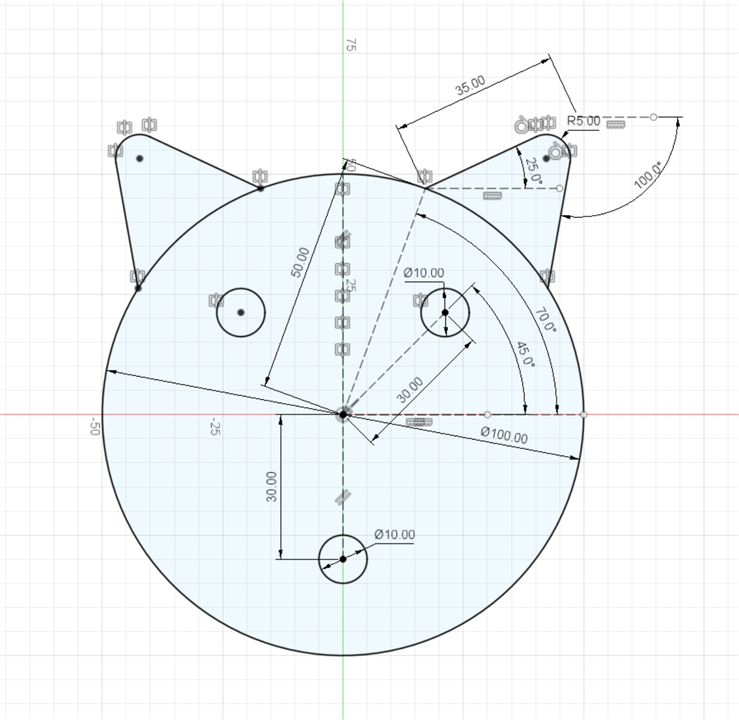
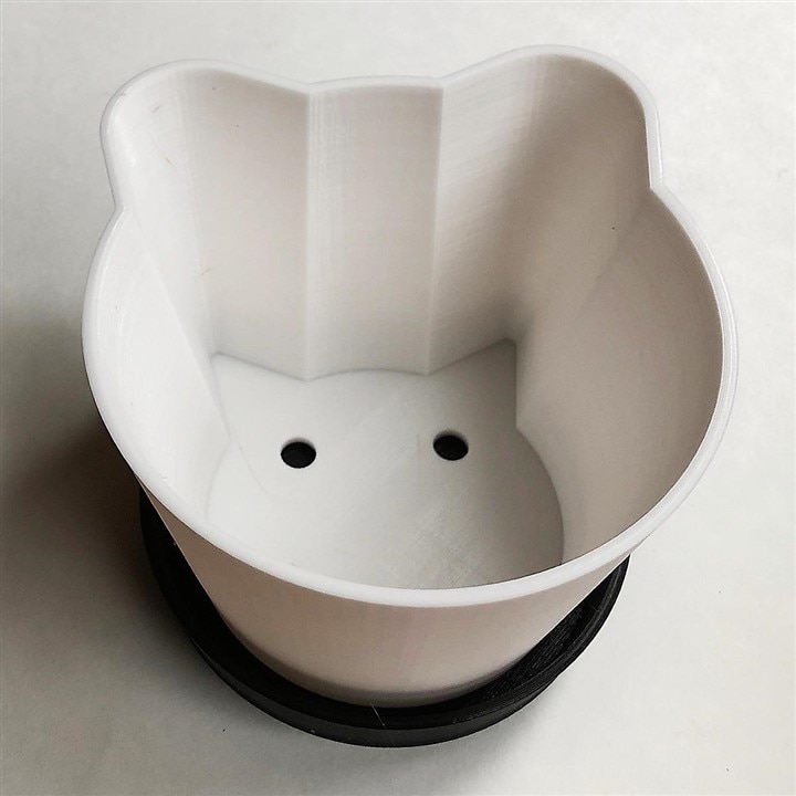
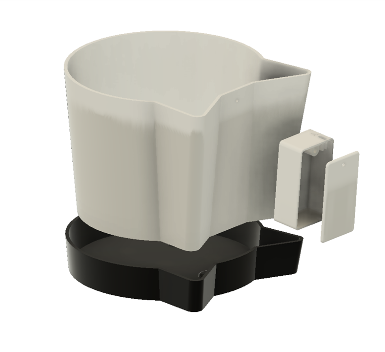
A flower pot is easy enough to make in Fusion 360. First, sketch a cat using circles and triangles. Be sure to draw eyes and a mouth that will become the drainage holes.
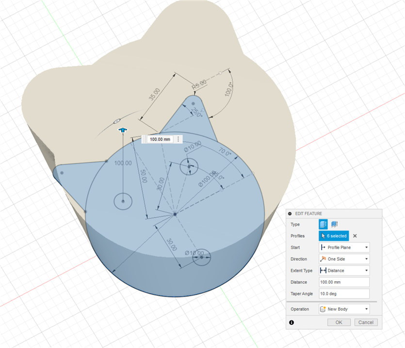
Then extrude the drawing and hollow it out using the shell tool. Make it about 3mm thick and add a 10-degree taper just to be fancy.
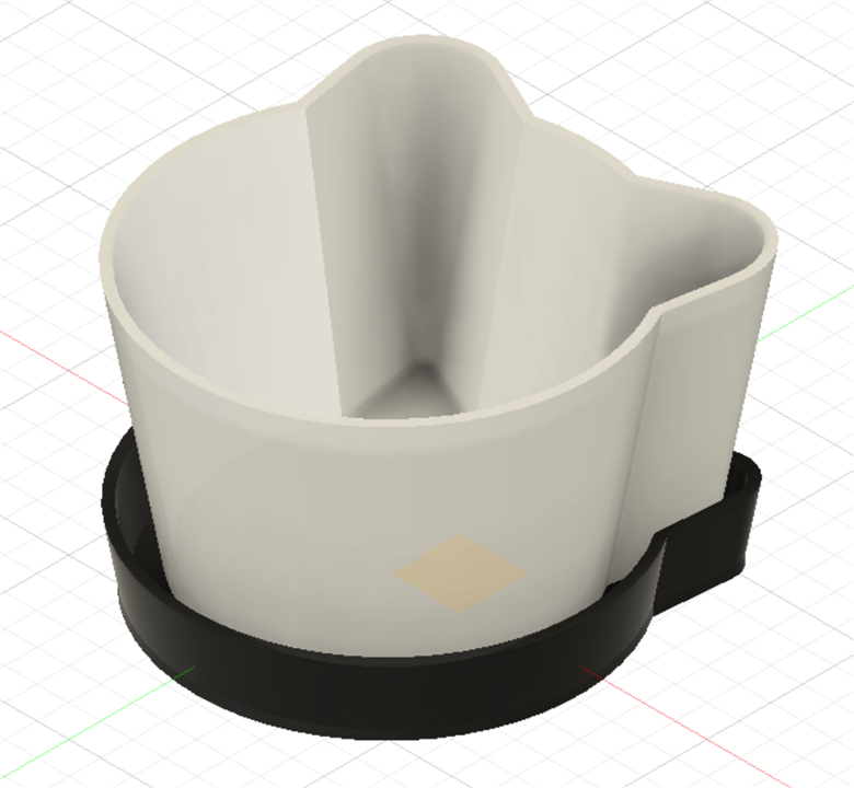
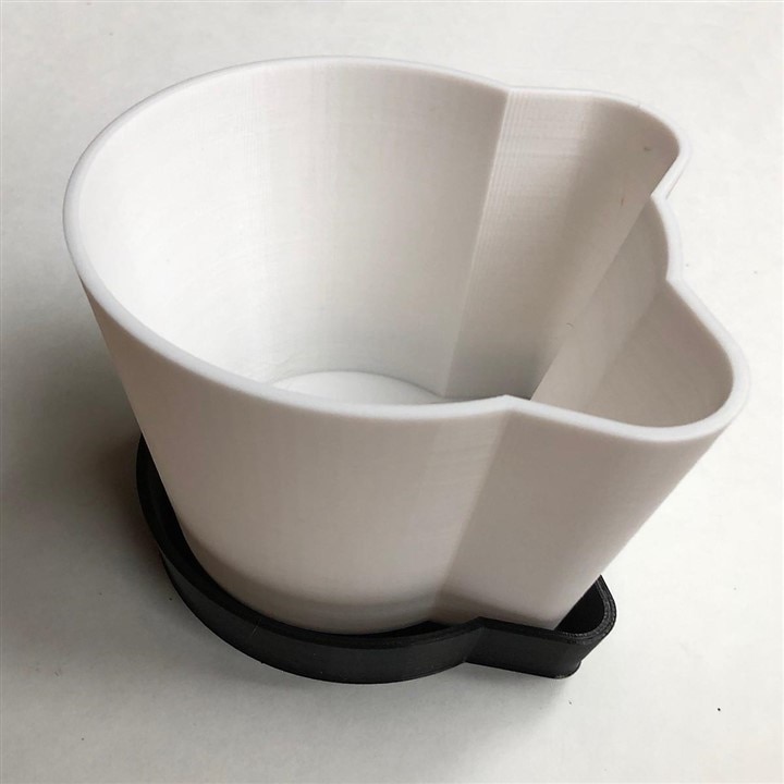
Then make a drip tray in the same shape. Here it is rendered in the model.
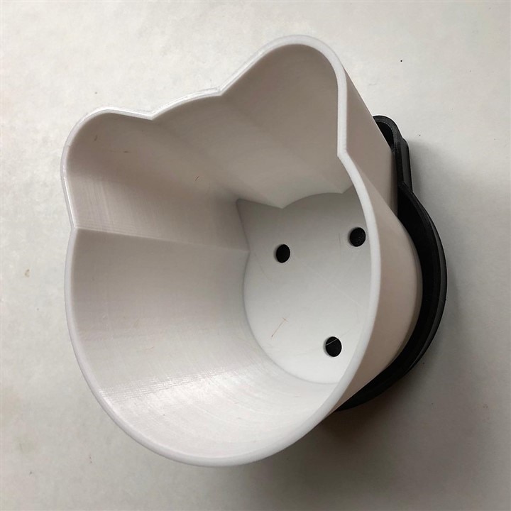
OK, time to print. Maybe PLA isn't the best choice for something exposed to wet soil but that is what I'll use. We'll see how long it lasts.
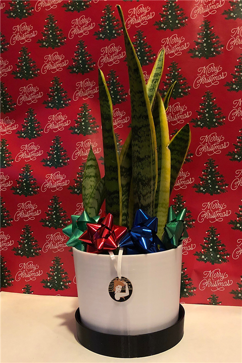
| The Cat Lover's Flower Pot |
|---|
|
|
|
Evaluating Moisture Sensors
What about some electronics? Doesn't she need to be told when to water the plant? There are lots of posts and videos on the internet about monitoring soil moisture with an Arduino but there is always room to add one more.
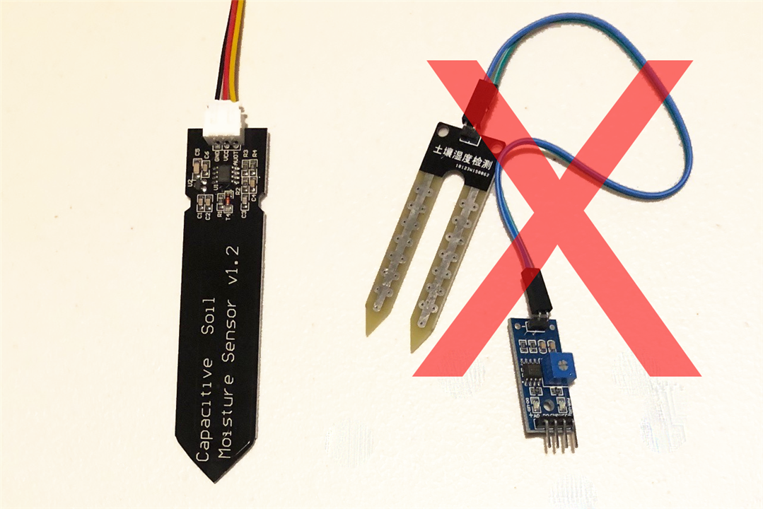
First, don't get the ones that measure the resistance across the soil. They eventually corrode and fail due to electrolysis. Get the ones that measure capacitance.
I was pleased to see that the sensor has a 555 timer on it! Let's look into the circuit. The schematic below makes what is happening clear.

The schematic shows a 555 timer outputting a square wave at ~1.5 MHz (some of them apparently have an older NE555 and operate at a lower frequency).

On my sample, I see a rough square wave ~1.6MHz with a 34% duty cycle and 3V3 amplitude on pin 3. There is a 3V3 regulator in the circuit which is not shown on the schematic above.
The next section of the circuit is an RC low pass filter using R1 and traces on the sensor PCB as a capacitor that is stuck into the soil. This low pass filter also acts as an integrator. When the square wave rises, it causes the voltage across the capacitor formed by the traces to rise. When the square wave goes low the capacitor formed by the traces discharges in a roughly triangular pattern. Here it is on the oscilloscope.

Of interest, the amplitude is only about 2V. I suspect the capacitance of my 'scope probes has loaded it down. Note the typical shape of an RC circuit and that the rise time is shorter overall due to the duty cycle of the square wave.
The last stage is the peak detector. When voltage is higher than the forward voltage of the diode T4 it is forward biased. T4 prevents backward current flow. The peak detector works by storing voltage in C4 and only releasing it slowly through the large resistor R4. In the 'scope capture below the output of the sensor is shown to be 2V7 in open air.

The two-minute video below is a further demonstration including insertion into water.
Electronic Design
The electronics are exceedingly simple and are shown in the image below.

The microcontroller is a D1 Mini ESP32 powered directly from 3 AAA batteries (4.5V) wired to Vcc and GND. The D1 Mini ESP32 has an LDO on board that drops the voltage down to 3V3. Be sure to remove the batteries when powering the microcontroller from USB. The capacitive soil moisture sensor is then wired with power (red) to 3V3 on the microcontroller and GND (black) to GND. I chose to receive data (yellow) on pin 34 of the microcontroller which can access 12-bit ADC on channel 1. In any case, it is best to use a pin accessing ADC channel 1 because channel 2 is not accessible when using WiFi.
Arduino Code
There isn't much needed in terms of code to use this with an Arduino.
/* Soil Moisture Analyzer v0.3
 *
 *  Developed with Wemos D1 Mini ESP32 and Capacitive Soil Moisture Sensor v1.2
 *  Posts data to AdafruitIO
 *
 *  December 2021
 *  fmilburn
 *
 *  This code is in the public domain
 */

#include <Arduino.h>
#include "Secrets.h"
#include <WiFi.h>
#include <Wire.h>
#include "Adafruit_MQTT.h"
#include "Adafruit_MQTT_Client.h"

// WiFi
char ssid[] = SECRET_SSID;        // network SSID (name)
char pass[] = SECRET_PASS;        // network password

// AdafruitIO
#define AIO_SERVER "io.adafruit.com"
#define AIO_SERVERPORT 1883
#define AIO_USERNAME SECRET_AIO_USERNAME // Your AdafruitIO username
#define AIO_KEY SECRET_AIO_KEY           // Your AdafruitIO key

WiFiClient client;

Adafruit_MQTT_Client mqtt(&client, AIO_SERVER, AIO_SERVERPORT, AIO_USERNAME, AIO_KEY);
Adafruit_MQTT_Publish moistureData = Adafruit_MQTT_Publish(&mqtt, AIO_USERNAME "/f/moisture_analyzer");

// Global constants
const bool DEBUG = false;
const unsigned long SLEEP_TIME = 30 *60 * 1000000; // time in us
const int SENSOR_PIN = 34;

// -----------------------------------------------------------------
// setup
// -----------------------------------------------------------------
void setup(){

  pinMode(BUILTIN_LED, OUTPUT);
  digitalWrite(BUILTIN_LED, HIGH);

  if (DEBUG) {
    Serial.begin(115200);
    delay(1000);
    Serial.println("Waking up");
  }

  pinMode(SENSOR_PIN, INPUT);
  adcAttachPin(SENSOR_PIN);
  analogReadResolution(12);

  // Take 10 raw readings, toss the first seven, average last 3
  int moistureValue = 0;
  for(int i = 0; i < 10; i++){
    int value = analogRead(SENSOR_PIN);
    if (i > 6) {
      moistureValue+= value;
    }
  }
  moistureValue = moistureValue / 3;

  // convert raw value to % water content
  moistureValue = map(moistureValue, 3500, 1500, 0, 100);
  if (DEBUG) {
    Serial.print("Soil Moisture is  = ");
    Serial.print(moistureValue);
    Serial.println("%");
  }

  // Publish the data
  startWiFiClient();
  MQTT_connect();
  moistureData.publish(moistureValue);
  while (!moistureData.publish(moistureValue)) {
    delay(100);
  }

  if (DEBUG) {
    Serial.println("Going to sleep");
    Serial.flush();
  }

  digitalWrite(BUILTIN_LED, LOW);

  // Sleep
  esp_sleep_enable_timer_wakeup(SLEEP_TIME);
  esp_deep_sleep_start();

}

// -----------------------------------------------------------------
// loop
// -----------------------------------------------------------------
void loop() {
  // never called
}

// -----------------------------------------------------------------
// startWiFiClient
// -----------------------------------------------------------------
void startWiFiClient(){

  if (DEBUG == true){
    Serial.print("\nConnecting to: ");
    Serial.print(ssid);
  }

  WiFi.begin(ssid, pass);
  while ( WiFi.status() != WL_CONNECTED) {
    // wait for connection
  }

  if (DEBUG == true){
    Serial.println("\nWiFi connected");
    Serial.print("IP address: ");
    Serial.println(WiFi.localIP());
  }
}

// -----------------------------------------------------------------
// MQTT_connect
// -----------------------------------------------------------------
void MQTT_connect() {

  if (DEBUG) {
    Serial.println("Trying to connect to Adafruit IO");
  }

  // Return if already connected
  int8_t again;
  if (mqtt.connected()) {
    return;
  }

  uint8_t retry = 5;
  while ((again = mqtt.connect()) != 0) {
    if (DEBUG){
      Serial.println(mqtt.connectErrorString(again));
    }
    mqtt.disconnect();
    delay(5000);
    retry--;
    if (DEBUG) {
      if (retry == 0){
        Serial.println("Unable to connect to AdafruitIO");
      }
      else {
        Serial.print("Connected after ");
        Serial.print(6 - retry);
        Serial.println(" attempts");
      }
    }
  }
}
The code is straight forward but here is a brief outline of how it works:
- Raw data from the sensor is converted to a moisture value as described in the section on calibration below
- Moisture values are posted to AdafruitIO where they can be plotted and out of range messages emailed to the user
- ESP32 "deep sleep" is used to minimize power - this results in all code residing in setup() upon wake-up and loop() never being called
- There is a lot of debugging Serial code which was left in and can be activated by making the variable DEBUG true.
AdafruitIO
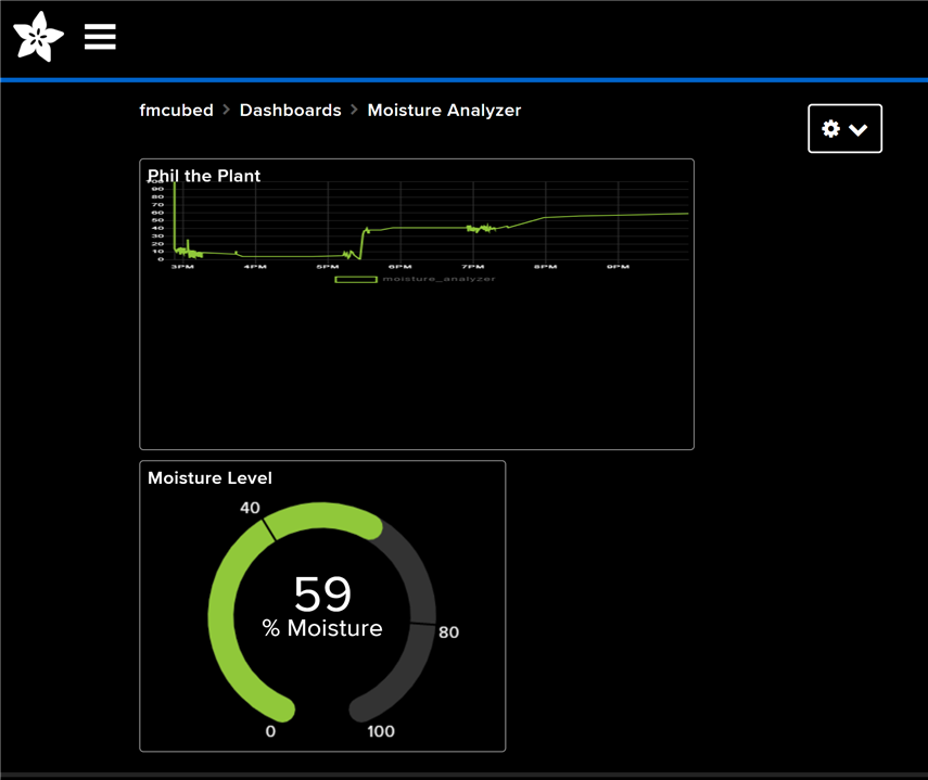
AdafruitIO was used to graphically present the data and send messages to the user when limits are exceeded. It is free (with restrictions) but easy to use and met the needs of this project. A 7-day graph and meter were selected for the user interface/dashboard. I decided to call the plant Phil.
Adafruit has extensive training on use such as that found here.
Calibration
I wanted to report the moisture value in a range from 0 to 100% although this isn't strictly necessary. The methodology used was to read the output of the sensor in air as well as immersed in water. These results are then mapped to a range of 0 to 100 in the Arduino code. The video below demonstrated capturing the raw data and shows AdafruitIO working.
Fabrication and Assembly
Three days prior to the project due date I leisurely resized the pot and tray, designed an electronic enclosure, and started 40 hours of 3D printing. The revised flower pot was the largest thing I've ever printed volumetrically. Fortunately, this went off without a hitch.
I'm a mechanical engineer who once was a teaching assistant for a university structural design course. I really should have put a rim on the top for extra strength and put fillets on the inside corners between the sides and bottom of the pot. Eh, probably not important.
While it was printing I soldered up the electronics, crimped some DuPont connectors, and started what should have been the trivial assembly of the electronics enclosure with one day to go. You may be thinking to yourself, how could he screw that up? Many ways of course. I used epoxy to fully coat the sensor and also to make the electronics enclosure water-resistant. Unfortunately, epoxy got into the DuPont connectors of the sensor due to a dumb decision on my part. I really wanted to be able to detach the sensor if it needed replacement, and I only had one, so on Christmas Eve I started snipping the old connector apart and to my surprise and relief was able to clean up the connector and put a new housing on it.

Of course, that wasn't the end of my problems. In my haste to get things glued up, I epoxied the microcontroller in place on the 3D print without removing the power on LED which I wanted to remove for power savings. Not being able to use the hot air reflow due to proximity to PLA I bludgeoned the LED off with my soldering iron taking a pad off along with it.
The sad part of this was I knew to tape off things I didn't want to be contaminated with epoxy and had thought to myself the day before that I needed to remove the LED before attaching it to the enclosure. However, I was "saving time" by launching into a job with quick-setting epoxy without carefully thinking things through beforehand.
Conclusion
In the end, everything was working was hours to go. I even had time to make a short video with Robot Santa and Bender giving commentary on the completed project.
See a write-up of my other Christmas creation, Robot Santa, here.
Thanks for reading! Your comments, corrections, and suggestions are always welcome.

