


Hello Everyone, My name is Harji Nagi. I am currently a third year student studying electronics and communication engineering from Pranveer Singh Institute Of Technology, Kanpur(Uttar Pradesh, India).I have a keen interest in robotics, Arduino, Embedded system, internet of things, FPGA and Analog electronics.
Today I made a diy smart greeting card for Element 14 which consist of three unique features in just one card .First feature is based on ISD1820 a small Voice Recorder and Playback module that can do the multi-segment recording application with the adjustment of the on-board resistor. Second feature consist of MPU-6050MPU-6050 for controlling 4 LEDs on the card. The gyroscope is programmed to detect the tilt in the card and then turn on the respective tilted LED and third feature is based on a two clap servo control, whenever the user clap two times, sensor detect sound, it make the servo rotate at about an degree of 150. This in turns turn on a LED to make the user sure about the direction of the servo. When a similar sound is produced again, then, it brings the servo to its original place, turning the LED off.
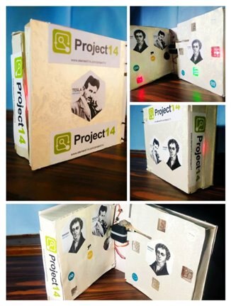
These three features makes the card unique, the user will definitely have a fun smile on using this card.
Components Required are:
1) 2 *Arduino Nano
2) MPU-6050MPU-6050
3) ISD 1820 voice record and playback module
4) 8 ohm speaker
5) 100 ohm resistors
6) 3* 18500 lithium battery 3.7 V
7) Battery Holder
8) Some LED's
9) Sound Sensor
10) Perf Boards
11) 4* 1.5 inch window hinges
12) Some 1 inches screws
13) Mg995 Servo motor
14) 2* Popsicle Sticks
15) small L bracket
16) Cello Tape, double sider tape, insulation tape
17) Glue Gun
18) Wires
19) Thermocol
20) Colorful Chart Papers
21) Plastic Zip Ties
Connection Diagram for controlling Leds:

LEDs :-const int frontLed = 3;const int bottomLed = 5;const int rightLed = 6;const int leftLed = 9;
And for the https://www.element14.com/community/view-product.jspa?fsku=1864742&nsku=37T8113&COM=noscriptMPU-6050. The https://www.element14.com/community/view-product.jspa?fsku=1864742&nsku=37T8113&COM=noscriptMPU-6050 must be connected to ground and 5V+, after that connect SDA to A4 (analog 4), SCL to A5(analog 5).
You are done with the connections now.
Before uploading the code you would require to download 2 libraries.
1. https://www.i2cdevlib.com/usage
2. https://playground.arduino.cc/Main/MPU-6050
Upload the code after doing the required connections.
Code for gyro control LED's :
/**
 * Simple implementation false
 *
 * means that for  pitch/yaw there only be
 * a single led for each direction. The led will get more bright
 * as the direction increases
 *
 * Simple implementation true
 * means that for pitch/yaw there will be multiple led's that light up one by one
 *
 * The accelerometer/gyro is a MPU6050, it should be wired to the SDA and SCL pins
 */
#define SIMPLE_IMPLEMENTATION false


const int frontLed = 3;
const int bottomLed = 5;
const int rightLed = 6;
const int leftLed = 9;
long int lastPrintTime;


typedef struct
{
    byte pin;
    byte positionInsideGroup;
    char thePosition; // Left, Right, Up, Down
    byte minAngle;
    byte maxAngle;
} ledConfig;


ledConfig leds[] = {
    {3, 1, 'u', 31, 45},
    {12, 2, 'u', 16, 30},
    {11, 3, 'u', 5, 15},
    {5, 1, 'd', 5, 15},
    {6, 2, 'd', 16, 30},
    {7, 3, 'd', 31, 45},
    {8 , 1, 'r', 5, 23},
    {9, 2, 'r', 24, 45},
    {10, 1, 'l', 5, 23},
    {4, 2, 'l', 24, 45},
};


#include "I2Cdev.h"
#include "MPU6050_6Axis_MotionApps20.h"
#if I2CDEV_IMPLEMENTATION == I2CDEV_ARDUINO_WIRE
    #include "Wire.h"
#endif


MPU6050 mpu;


bool dmpReady = false;  // set true if DMP init was successful
uint8_t mpuIntStatus;   // holds actual interrupt status byte from MPU
uint8_t devStatus;      // return status after each device operation (0 = success, !0 = error)
uint16_t packetSize;    // expected DMP packet size (default is 42 bytes)
uint16_t fifoCount;     // count of all bytes currently in FIFO
uint8_t fifoBuffer[64]; // FIFO storage buffer


// orientation/motion vars
Quaternion q;           // [w, x, y, z]         quaternion container
VectorInt16 aa;         // [x, y, z]            accel sensor measurements
VectorInt16 aaReal;     // [x, y, z]            gravity-free accel sensor measurements
VectorInt16 aaWorld;    // [x, y, z]            world-frame accel sensor measurements
VectorFloat gravity;    // [x, y, z]            gravity vector
float euler[3];         // [psi, theta, phi]    Euler angle container
float ypr[3];           // [yaw, pitch, roll]   yaw/pitch/roll container and gravity vector
volatile bool mpuInterrupt = false;     // indicates whether MPU interrupt pin has gone high


void setup()
{
    #if I2CDEV_IMPLEMENTATION == I2CDEV_ARDUINO_WIRE
        Wire.begin();
        TWBR = 24; // 400kHz I2C clock (200kHz if CPU is 8MHz)
    #elif I2CDEV_IMPLEMENTATION == I2CDEV_BUILTIN_FASTWIRE
        Fastwire::setup(400, true);
    #endif


    Serial.begin(9600);
    while (!Serial); // wait for Leonardo enumeration, others continue immediately
    Serial.println(F("Initializing I2C devices..."));
    mpu.initialize();
    Serial.println(F("Testing device connections..."));
    Serial.println(mpu.testConnection() ? F("MPU6050 connection successful") : F("MPU6050 connection failed"));
    Serial.println(F("Initializing DMP..."));
    devStatus = mpu.dmpInitialize();
    mpu.setXGyroOffset(220);
    mpu.setYGyroOffset(76);
    mpu.setZGyroOffset(-85);
    mpu.setZAccelOffset(1788); // 1688 factory default for my test chip
    if (devStatus == 0) {
        // turn on the DMP, now that it's ready
        Serial.println(F("Enabling DMP..."));
        mpu.setDMPEnabled(true);
        Serial.println(F("Enabling interrupt detection (Arduino external interrupt 0)..."));
        attachInterrupt(0, dmpDataReady, RISING);
        mpuIntStatus = mpu.getIntStatus();
        Serial.println(F("DMP ready! Waiting for first interrupt..."));
        dmpReady = true;
        packetSize = mpu.dmpGetFIFOPacketSize();
    } else {
        Serial.print(F("DMP Initialization failed (code "));
        Serial.print(devStatus);
        Serial.println(F(")"));
    }
    if (SIMPLE_IMPLEMENTATION) {
        initializeLEDsSimple();
    } else {
        initializeLEDsMultiple();
    }
    lastPrintTime = millis();
}


void loop()
{
    if (!dmpReady) return;
    mpuInterrupt = false;
    mpuIntStatus = mpu.getIntStatus();
    fifoCount = mpu.getFIFOCount();
    if ((mpuIntStatus & 0x10) || fifoCount == 1024) {
        mpu.resetFIFO();
        Serial.println(F("FIFO overflow!"));
    } else if (mpuIntStatus & 0x02) {
        while (fifoCount < packetSize) {
          fifoCount = mpu.getFIFOCount();
        }
        mpu.getFIFOBytes(fifoBuffer, packetSize);
        fifoCount -= packetSize;
        mpu.dmpGetQuaternion(&q, fifoBuffer);
        mpu.dmpGetGravity(&gravity, &q);
        mpu.dmpGetYawPitchRoll(ypr, &q, &gravity);
        int x = ypr[0] * 180/M_PI;
        int y = ypr[1] * 180/M_PI;
        int z = ypr[2] * 180/M_PI;
        Serial.print(y);Serial.print("\t");Serial.println(z);
        if (SIMPLE_IMPLEMENTATION) {
            flashLEDsSimple(x, y, z);
        } else {
            flashLEDsMultiple(x, y, z);
        }
    }
}


void initializeLEDsSimple()
{
    pinMode(frontLed, OUTPUT);
    pinMode(bottomLed, OUTPUT);
    pinMode(rightLed, OUTPUT);
    pinMode(leftLed, OUTPUT);
}


void initializeLEDsMultiple()
{
    for (int i=0; i<10; i++) {
        Serial.println(leds[i].pin);
        pinMode(leds[i].pin, OUTPUT);
    }
    delay(3000);
}


void flashLEDsSimple(int x, int y, int z)
{
    if (y > 0) {
        analogWrite(rightLed, y*4);
        analogWrite(leftLed, 0);
    } else {
        analogWrite(leftLed, y*4*-1);
        analogWrite(rightLed, 0);
    }
    if (z > 0) {
        analogWrite(bottomLed, z*4);
        analogWrite(frontLed, 0);
    } else {
        analogWrite(frontLed, z*4*-1);
        analogWrite(bottomLed, 0);
    }
}


void flashLEDsMultiple(int x, int y, int z)
{
    for (int i=0; i<10; i++) {
        //Serial.print(z);Serial.print(",");Serial.print(leds[i].thePosition);Serial.print(",");Serial.println(leds[i].minAngle);
        bool modified = false;
        if (z < 0 && leds[i].thePosition == 'u' && abs(z) > leds[i].minAngle) {
            digitalWrite(leds[i].pin, HIGH);
            modified = true;
        }
        if (z > 0 && leds[i].thePosition == 'd' && abs(z) > leds[i].minAngle) {
            digitalWrite(leds[i].pin, HIGH);
            modified = true;
        }
        if (y < 0 && leds[i].thePosition == 'l' && abs(y) > leds[i].minAngle) {
            digitalWrite(leds[i].pin, HIGH);
            modified = true;
        }
        if (y > 0 && leds[i].thePosition == 'r' && abs(y) > leds[i].minAngle) {
            digitalWrite(leds[i].pin, HIGH);
            modified = true;
        }
        if (!modified) {
            digitalWrite(leds[i].pin, LOW);
        }
    }
}


void dmpDataReady()
{
    mpuInterrupt = true;
}
Connections for ISD1820:
ISD1820 must be connected to ground and its operating voltage is 2.2V to 5V.And connect the speaker at sp+ and sp- .
Press the red button(rec) to start recording the song, voice or any greeting message. It will record not more than 20 seconds.
After recording press Playback to play the recorded message.

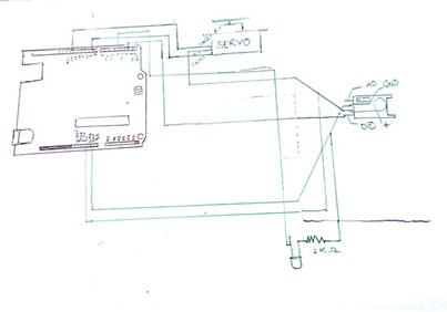
Circuit diagram for 2 Clap Servo Control:
Code for 2 Clap Servo Control:
#include <Servo.h>
Servo myservo;
int pos = 10;
int Sensor = A0;
int clap = 0;
long detection_range_start = 0;
long detection_range = 0;
boolean status_lights = false;
void setup() {
  myservo.attach(9);
pinMode(Sensor, INPUT);
pinMode(10,OUTPUT);


}
void loop() {
int status_sensor = digitalRead(Sensor);
if (status_sensor == 0)
{
if (clap == 0)
{
detection_range_start = detection_range = millis();
clap++;
}
else if (clap > 0 && millis()-detection_range >= 50)
{
detection_range = millis();
clap++;
}
}
if (millis()-detection_range_start >= 400)
{
if (clap == 2)
{
if (!status_lights)
{
status_lights = true;
digitalWrite(10, HIGH);
for (pos = 10; pos <= 150; pos += 1)
{
    myservo.write(pos);
    delay(15);
}
  }
else if (status_lights)
{
status_lights = false;
digitalWrite(10, LOW);
for (pos = 150; pos >= 0; pos -= 1) { // goes from 90 degrees to 0 degrees
    myservo.write(pos);              // tell servo to go to position in variable 'pos'
    delay(15);
}
}
clap = 0;
}
}
}
Now place all the electronic components and do the connection according to the schematic diagram. And apply cello tape so as the component remain fixed in their position


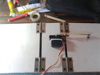
Now cut the perf board according to the size of the thermocol and mount the servo motor on it with the help of plastic zip ties.
Make the movable joint with help of popsicle sticks and apply glue gun to stick it with servo horns.
After mounting servo motor and movable joints place the thermocol sheet as per the picture given below and cover it with chart papers.

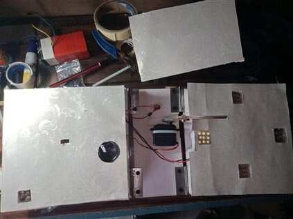
Now cover these components with the help of colorful chart papers and stickers to make it more attractive.


Now the card is ready .On switching on the power button the gyroscope detects the tilt in the card and then turn on the respective tilted LED Whenever the user the user clap two times, sensor hears any sound under its range, it make the servo rotate at about an degree of 150. This in turns turn on a LED to make the user sure about the direction of the servo. When a similar sound is produced again, then, it brings the servo to its original place, turning the LED off. and on pressing the playback button of ISD1820, it plays a melodious song. Please watch this video for more information. I hope you enjoyed this tutorial.