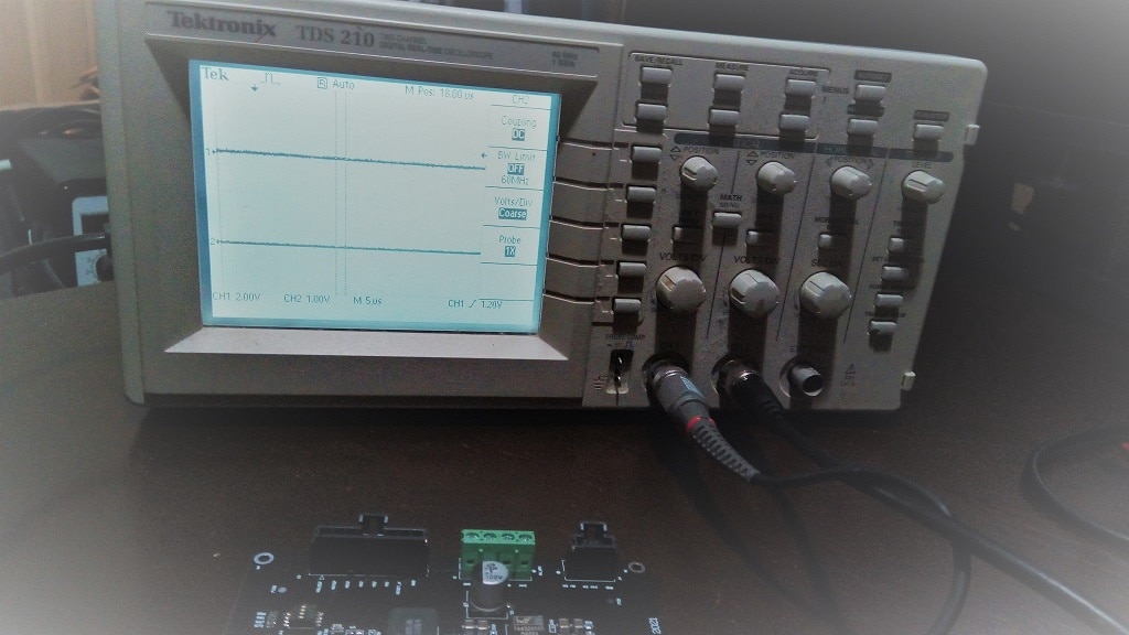
Recently I implemented a custom power supply for an IOT system. The requirement needed was to provide at least 2.5A to fully power on a RPI SBC for a control and monitor solution as well as a 24V output for powering a stepper motor.
1. Design
The requirements for the power supply were as follows:
- a) Wide input range. The power supply is supposed to operate from a Li-Ion battery bank so the voltage can be from 30V to 55V.
- b) Output current : 2.5A
- c) Output ripple 50mV. Since the power supply will directly feed an RPI SBC, it needs to be relatively clean in order not to cause resets.
- d) Temperature stability: This is the most challenging requirements as the PS is supposed to operate outdoors. While not exposed to the elements, the system is subject to wide temperature differentials.
It is clear that for efficiency reasons one has to develop an SMPS solution. The issue is that due to the voltage input and current output requirements a custom adjustable switching regulator has to be used. This is mainly dictated by cost / efficiency as well as PS parameters. After searching some more I settled on the LMR16030PDDA. This IC comes in a hand solder-able 8pin SOIC and can output up to 3A.

Looking at the datasheet of the step down regulator the IC comes in an 8 pin SOIC package.

As it's a buck switching regulator it's exactly up to the hand at task. One issue I was expecting when dealing with the input voltage is a drop in efficiency. While 45-> 24V would be reasonable , a drop from 40V to 5V is a bit on the high side. normally a 12V SMPS output is used to feed the lower voltage rails. In this case however the IC can handle this. The IC comes with an integrated high side MOSFET so the external compensation network can be used to set the output voltage.
2. Assembly
After ordering the Parts and PCB, the following was hand assembled.

Next step is to start testing.

Continued: Part 2 - Testing
