


DIY SMD Breakout Board and Soldering Techniques
SMD soldering can be quite difficult for beginners. Although there are numerous videos on YouTube showing SMD soldering techniques, it takes time and practice to master the art of SMD soldering especially with the SMD ICs due to the large number of pins placed close to each other. In this blog, I will present a technique to create your own SMD breakout boards for SMD ICs. This method is simple and can be used by anyone who knows basic through-hole soldering. Before I start the DIY breakout board design, let us discuss the existing breakout boards or SMD to DIP adapters. Such adapters based on PCB technology are available in various online stores. They are quite helpful as the SMD chips are converted to DIP with the help of these adapters. However, one still has to solder the SMD device onto the PCB adapter.

DIY Breakout Board
To design the DIY breakout board, you'll need the following items -
| SMD IC |
| Prototyping PCB/Board |
| Multi stranded wire |
| Soldering iron/station |
| Solder wire |
| Male or female header pins 2.54 mm |
Steps to design the board -
First, start by preparing the prototyping board. Cut a small piece of the board such that it can fit the DIP version of the SMD IC. For example, if you are designing
a breakout board for SOIC - 8 package, then cut a piece of the board such that it can fit the 8 pins of the DIP package.

The next step is to prepare the multi-stranded wire. This wire will act as the extended leads of the SOIC package. Make sure to use a multi-stranded wire as it is more flexible than a single-stranded wire and can withstand bends and twists. Remove the out insulation and twist all the strands. The tin the wire using solder. Tin enough length of the wire such that you get 'n' number of equal length pieces where n = the no. of leads on the SOIC package.
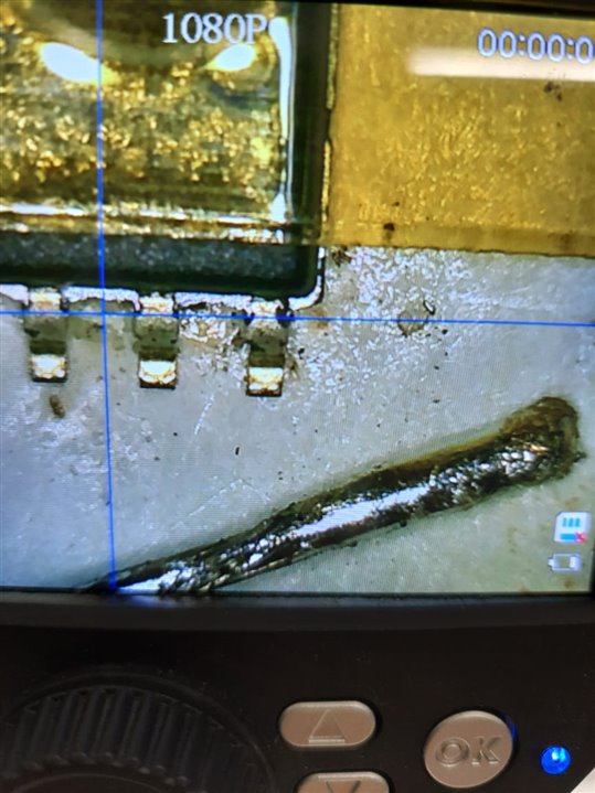
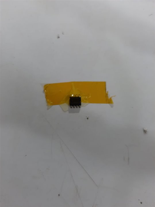
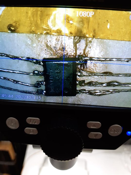
Then place the SOIC package on a flat surface and stick it firmly on the surface using blu tack or Kapton tape. Then start by soldering each piece of the inner wire to one lead of the SOIC at a time. Be gentle, just touch the tip of the soldering iron to the IC pins along with the tinned wire. Make sure that you're using the lowest possible temperature to do this. This shouldn't require much solder as the tinned wire has enough solder to stick to the leads of the SOIC package.
Once all the pins of the SOIC are soldered with the wires you can use the SMD IC in this form. However, I prefer going one step further and creating an SMD to DIP breakout board/adapter.
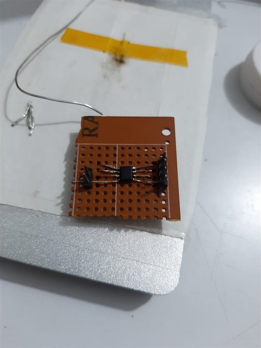
Gently bend the wires soldered to the pins of the SOIC to a 90-degree angle. Use tweezers to do this and do not apply a lot of force. Next, spread these wires apart such that they can easily pass through the 2.54mm spacing on the prototyping board/perfboard. Now you'll understand the importance of using a multi-stranded wire instead of a single-stranded one. Multistranded wires are easier to play with, they can be bent and twisted many times before the break.
Next, place the SOIC on the perfboard and insert the wires through the holes. Solder these extended pins of the SOIC onto the perfboard to hold the IC firmly. Now, place the header pins in the adjacent rows on both sides and solder them to keep them in place. Now connect the wires of the SOIC and the header pins on the perfboard using solder. This will connect the SOIC pins with the header pins. You can use male or female headers as per your choice. This completes the design of the breakout board. You SOIC is ready to be used on perfboards or breadboards that only support DIP-packages.
Test the connections between the header pins and the SOIC pins using continuity tester/DMM.
Every method has certain limitations. This method is limited to SOIC and TQFP packages only. For packages like QFN, BGA, this method is not suitable, however, if you wish to try please try and let me know if it works perfectly. Another limitation is that this method is not good for RF or high-speed devices. Due to the extra wires and the breakout board, there will be a lot of parasitics such as stray capacitances and inductances and the IC may not perform as expected. Hence, for RF or high-speed SMD ICs, it is better to design a PCB with the actual layout of the IC and avoid any adapters or converters.