element14 Community
element14 Community
    Register Log In
  • Site
  • Search
  • Log In Register
  • About Us
  • Community Hub
    Community Hub
    • What's New on element14
    • Feedback and Support
    • Benefits of Membership
    • Personal Blogs
    • Members Area
    • Achievement Levels
  • Learn
    Learn
    • Ask an Expert
    • eBooks
    • element14 presents
    • Learning Center
    • Tech Spotlight
    • STEM Academy
    • Webinars, Training and Events
    • Learning Groups
  • Technologies
    Technologies
    • 3D Printing
    • FPGA
    • Industrial Automation
    • Internet of Things
    • Power & Energy
    • Sensors
    • Technology Groups
  • Challenges & Projects
    Challenges & Projects
    • Design Challenges
    • element14 presents Projects
    • Project14
    • Arduino Projects
    • Raspberry Pi Projects
    • Project Groups
  • Products
    Products
    • Arduino
    • Avnet Boards Community
    • Dev Tools
    • Manufacturers
    • Multicomp Pro
    • Product Groups
    • Raspberry Pi
    • RoadTests & Reviews
  • Store
    Store
    • Visit Your Store
    • Choose another store...
      • Europe
      •  Austria (German)
      •  Belgium (Dutch, French)
      •  Bulgaria (Bulgarian)
      •  Czech Republic (Czech)
      •  Denmark (Danish)
      •  Estonia (Estonian)
      •  Finland (Finnish)
      •  France (French)
      •  Germany (German)
      •  Hungary (Hungarian)
      •  Ireland
      •  Israel
      •  Italy (Italian)
      •  Latvia (Latvian)
      •  
      •  Lithuania (Lithuanian)
      •  Netherlands (Dutch)
      •  Norway (Norwegian)
      •  Poland (Polish)
      •  Portugal (Portuguese)
      •  Romania (Romanian)
      •  Russia (Russian)
      •  Slovakia (Slovak)
      •  Slovenia (Slovenian)
      •  Spain (Spanish)
      •  Sweden (Swedish)
      •  Switzerland(German, French)
      •  Turkey (Turkish)
      •  United Kingdom
      • Asia Pacific
      •  Australia
      •  China
      •  Hong Kong
      •  India
      •  Korea (Korean)
      •  Malaysia
      •  New Zealand
      •  Philippines
      •  Singapore
      •  Taiwan
      •  Thailand (Thai)
      • Americas
      •  Brazil (Portuguese)
      •  Canada
      •  Mexico (Spanish)
      •  United States
      Can't find the country/region you're looking for? Visit our export site or find a local distributor.
  • Translate
  • Profile
  • Settings
Circuit Prototype Techniques
  • Challenges & Projects
  • Project14
  • Circuit Prototype Techniques
  • More
  • Cancel
Circuit Prototype Techniques
Blog Pluggable Module Prototyping for Baluns and other Components
  • Blog
  • Forum
  • Documents
  • Events
  • Polls
  • Files
  • Members
  • Mentions
  • Sub-Groups
  • Tags
  • More
  • Cancel
  • New
Join Circuit Prototype Techniques to participate - click to join for free!
  • Share
  • More
  • Cancel
Group Actions
  • Group RSS
  • More
  • Cancel
Engagement
  • Author Author: shabaz
  • Date Created: 13 Mar 2022 3:30 AM Date Created
  • Views 10912 views
  • Likes 13 likes
  • Comments 5 comments
  • dip
  • balun
  • prototyping
  • rf
Related
Recommended

Pluggable Module Prototyping for Baluns and other Components

shabaz
shabaz
13 Mar 2022

Table of Contents

  • Introduction
  • What are Baluns?
  • Why Reconfigure?
  • Parts Used
  • Making a Circuit with the Multiple Balun Module
  • Replicating the Project
  • Other Ideas
  • Summary


Introduction


This blog is about how I went about prototyping with RF devices called baluns. I wanted to have a reconfigurable method that would allow me to mess about with different topologies. I have not added a video for this project, because I'd like to be disqualified from the competition. I'm not suggesting I would win anything, but I have already won an RF Project14 competition not that long ago so I'd prefer the judges consider other projects. The method described here is very similar to that used in the past with wire-wrap modules. It is also very similar to how Ethernet transformers are assembled. I used both of those concepts here basically.


What are Baluns?


They are interesting devices that behave almost like conventional transformers. The word balun is short for balanced-unbalanced. Unlike a transformer, there is not necessarily electrical isolation from the primary to the secondary side, for DC current. However, for AC common-mode current, there is a high resistance between the primary and secondary side. This sounds like a very degraded conventional transformer, however, it has a huge benefit in that the balun can work to extremely high frequencies, and can often work across a wide band. The project here was tested up to 50 MHz (I didn't test further), and it is possible to create baluns that operate at GHz values and beyond.

Why Reconfigure?


A balun on its own has uses, for instance, a good use-case is as its name implies, to interwork an unbalanced side (also known as ground referenced) to a balanced side, or vice-versa. However, if you combine more than one balun, you can do even more interesting stuff. As a result, it is highly desirable to be able to connect baluns in different configurations while experimenting. This blog post uses two baluns and some resistors to create a circuit that will split a signal into two, with one output inverted. A pluggable module method seemed attractive because there is also a desire to be able to swap out parts in order to tweak circuits. For instance, the baluns used in this project were found to not work very well at 100 kHz, and only worked well at 1 MHz and beyond. It would be nice to be able to swap out the baluns and try different ones to compare.


Parts Used


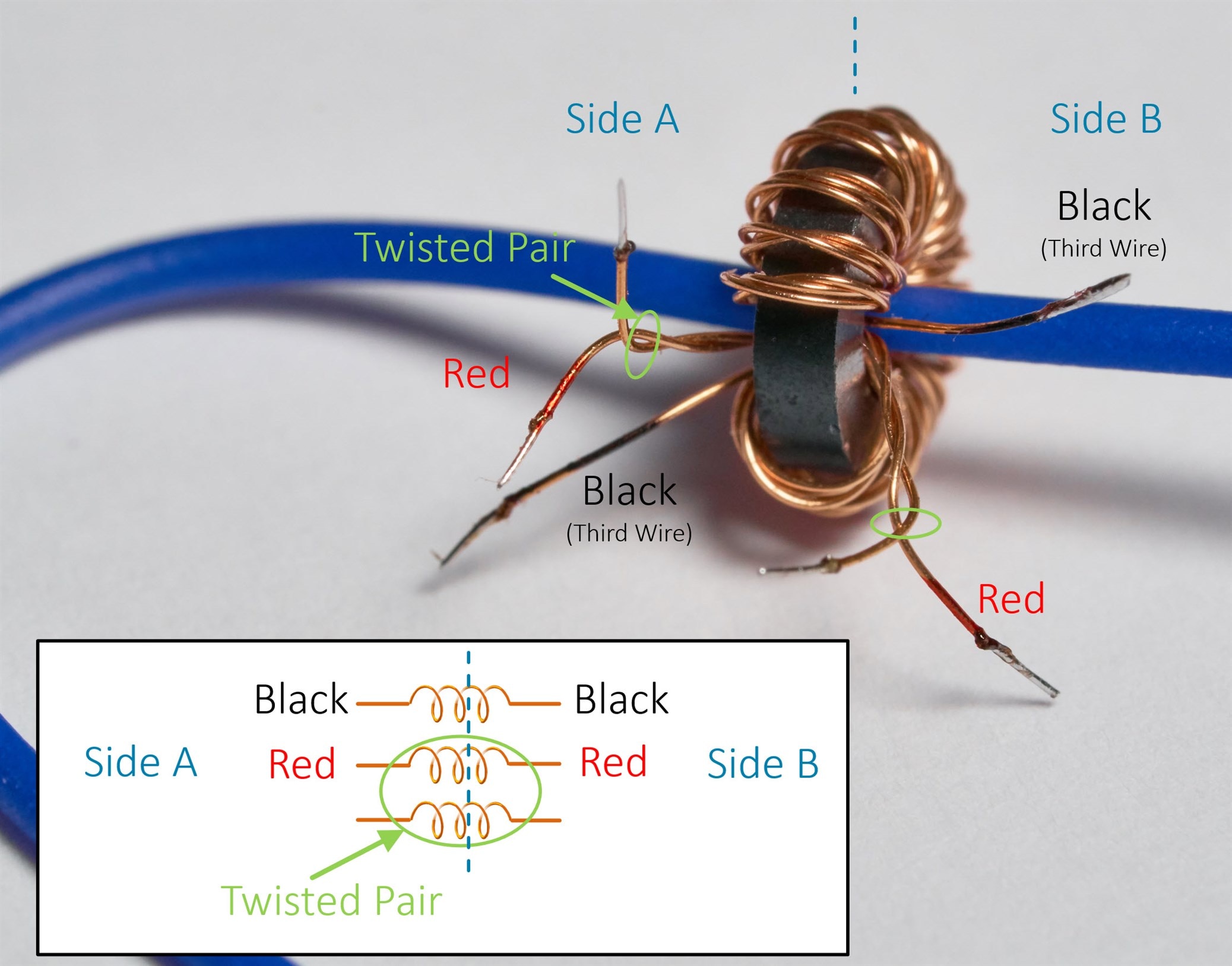
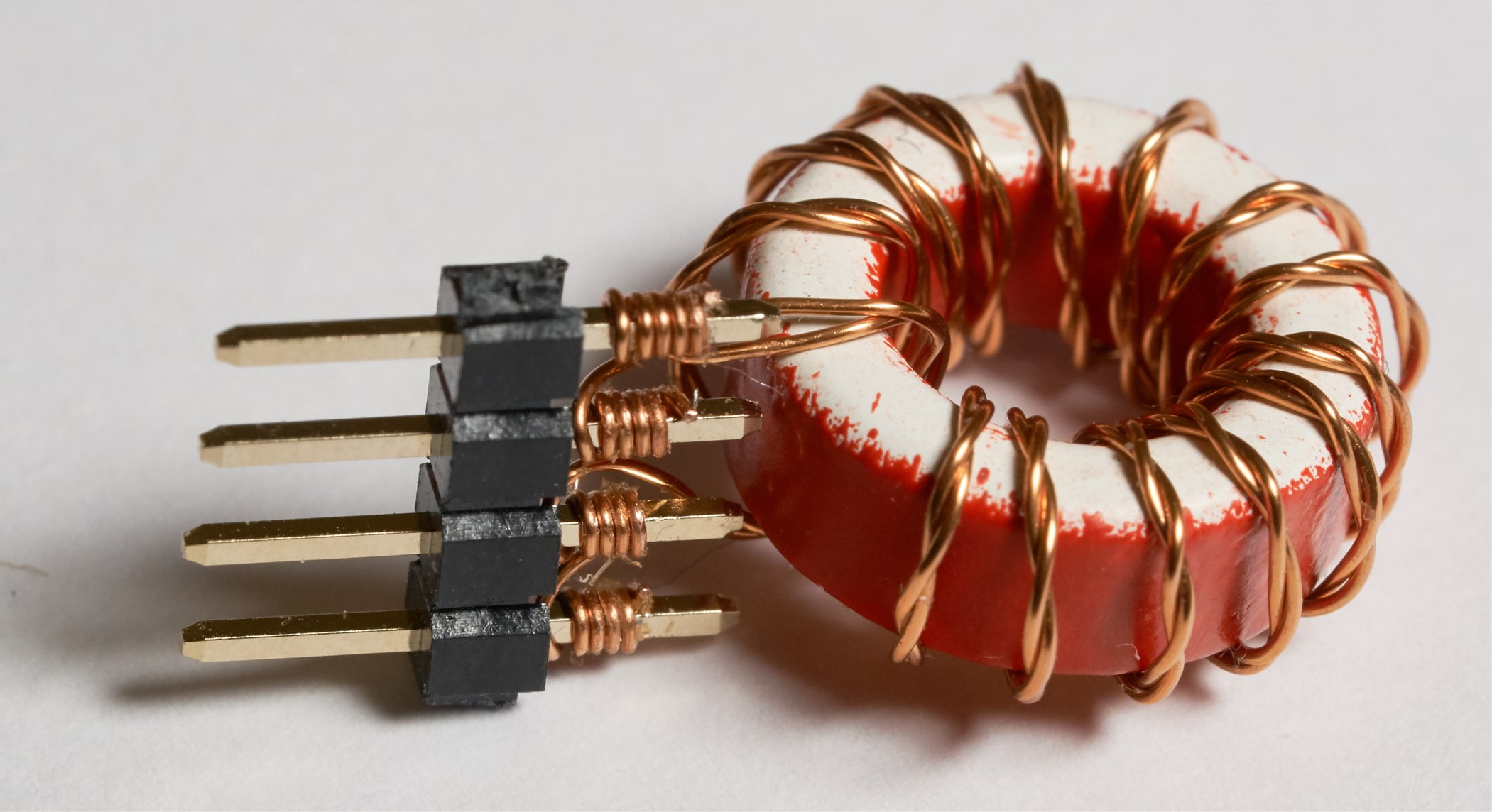
A balun was created by twisting two pieces of enameled copper wire and threading it through a toroid core multiple times. I created four such baluns, but for the fourth one, after I had twisted the wire pair, I then wrapped a third wire around it. It's beyond the scope of this blog post to discuss why such windings are required (because that's a rabbit hole), but if there's interest I'll write it up. Anyway, here is a photo of the fourth balun (these ferrite cores are small, so the blue solid-core wire in the photo is being used to prop it up; this support method also came in handy when I was heating the wire ends to remove the enamel). I used a multimeter set to continuity test mode to figure out which wire was which and then colored the end of the winding using a permanent marker pen.

image


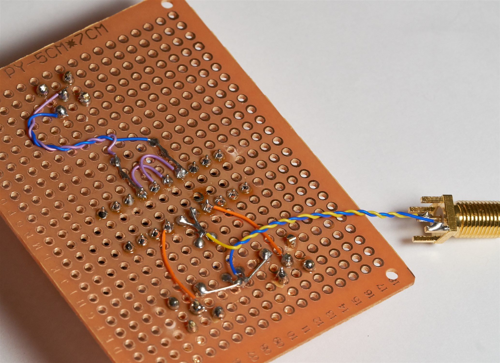
Next, I took an IDC DIP header used for ribbon cables and pulled off the plastic cover. I soldered the transformers onto it as shown here:

image

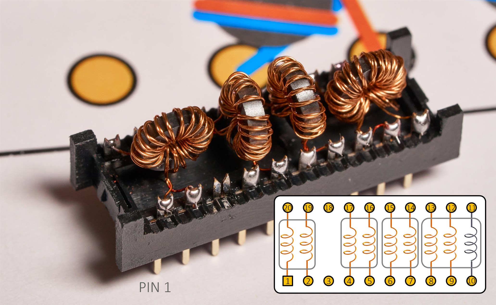
You can actually buy forked (and non-forked) DIP modules intended for soldering components, but they are more expensive, getting hard-to-find from distributors these days, and I didn't have any. The IDC DIP header worked fine. Anyway, my Balun Prototyping Module was complete!


Making a Circuit with the Multiple Balun Module


As a quick test, I assembled a circuit developed by C. L. Ruthroff in 1959 (in a paper simply called Some Broadband Transformers), known as a Hybrid:

image

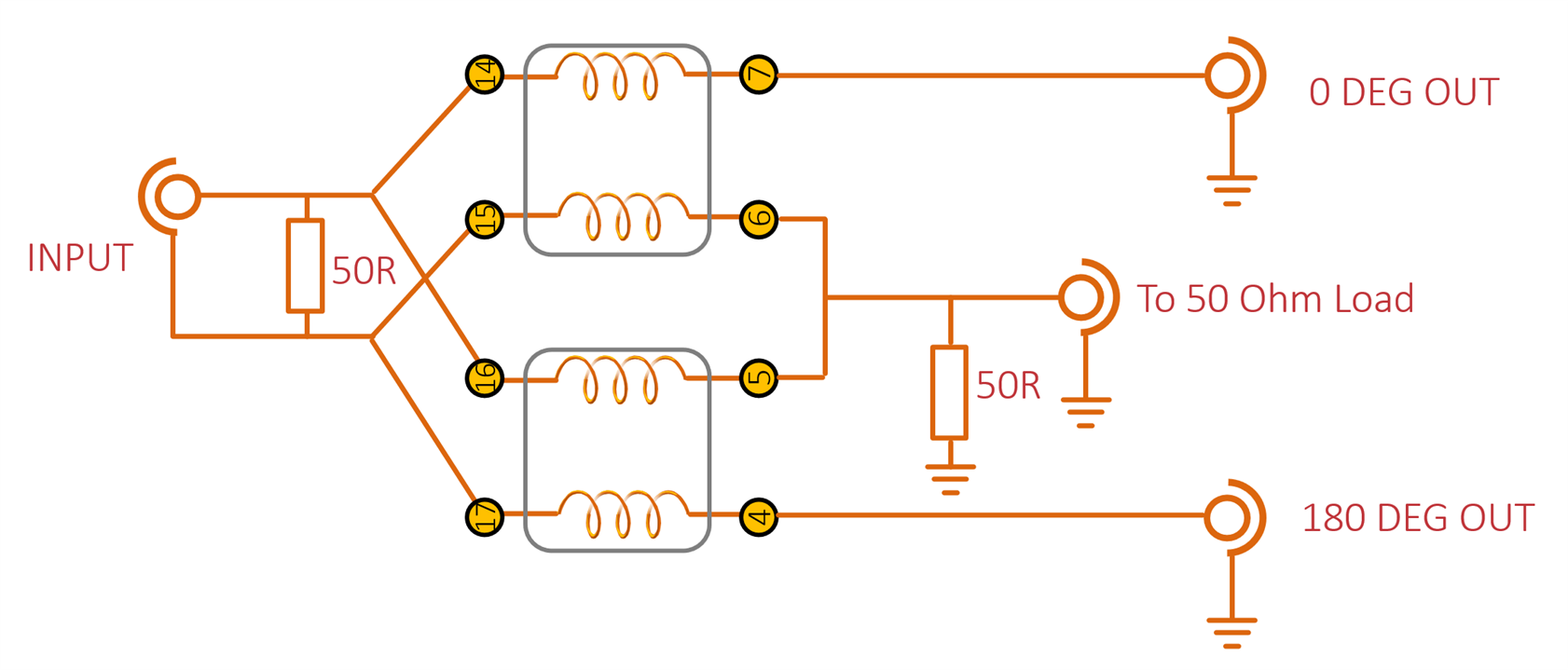
For this circuit, I just used the two center baluns in the module. Of course, the module can be unplugged if I want to try to swap out the baluns with a new design.

image

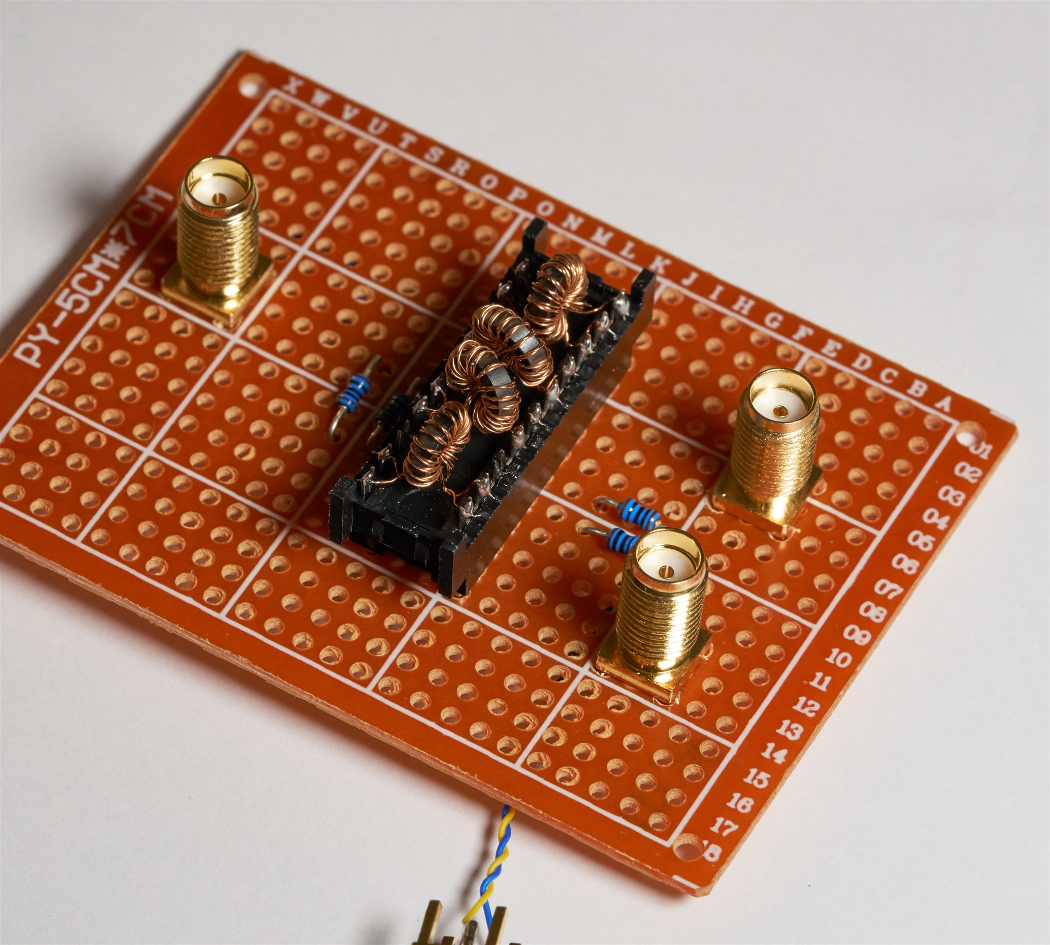
Here is the underside; one SMA connector is hanging off the board because I ran out of space on the small protoboard, I wanted to space the connectors out.

image


I hooked up the circuit to a signal generator and oscilloscope:

image

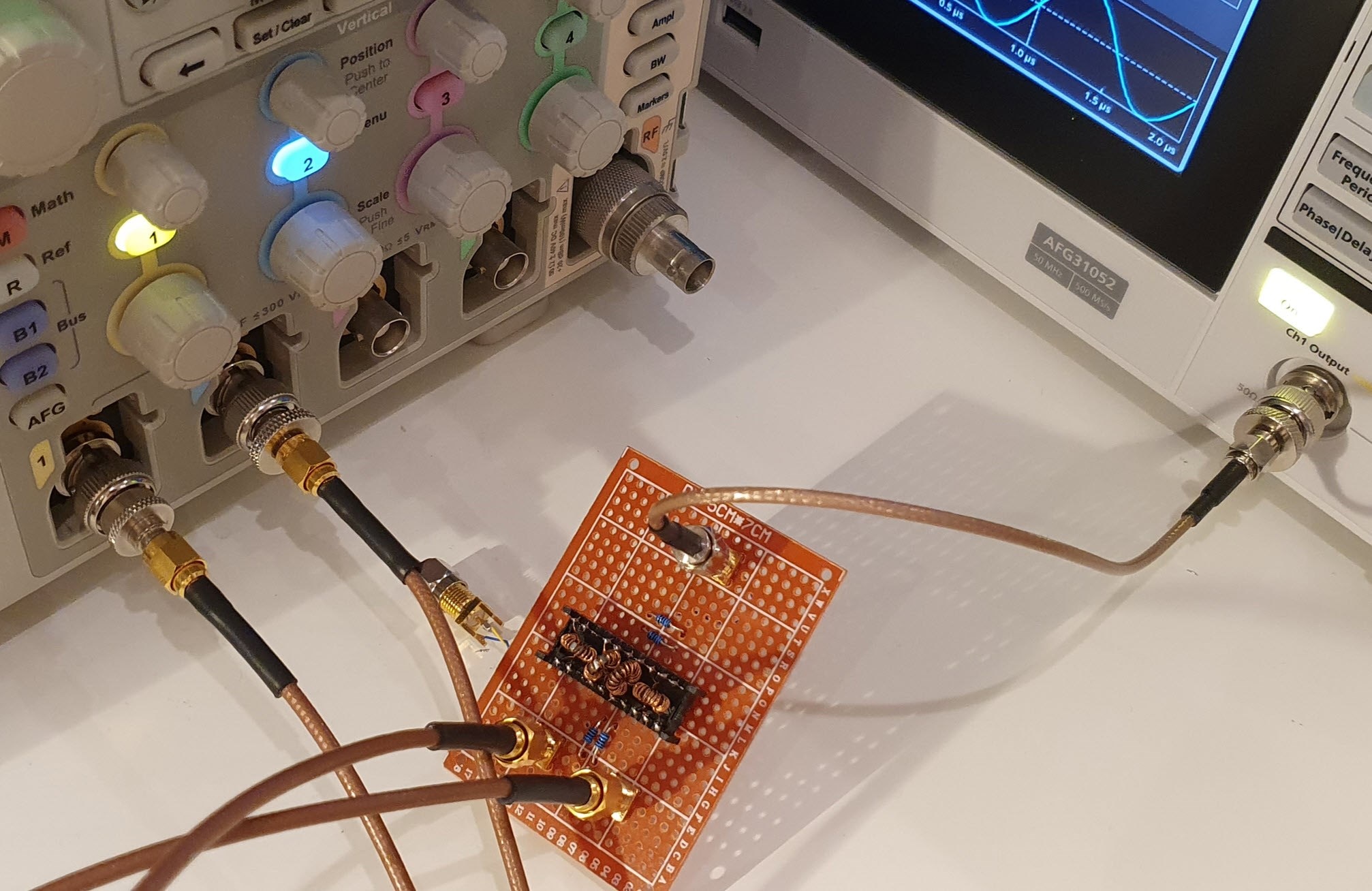
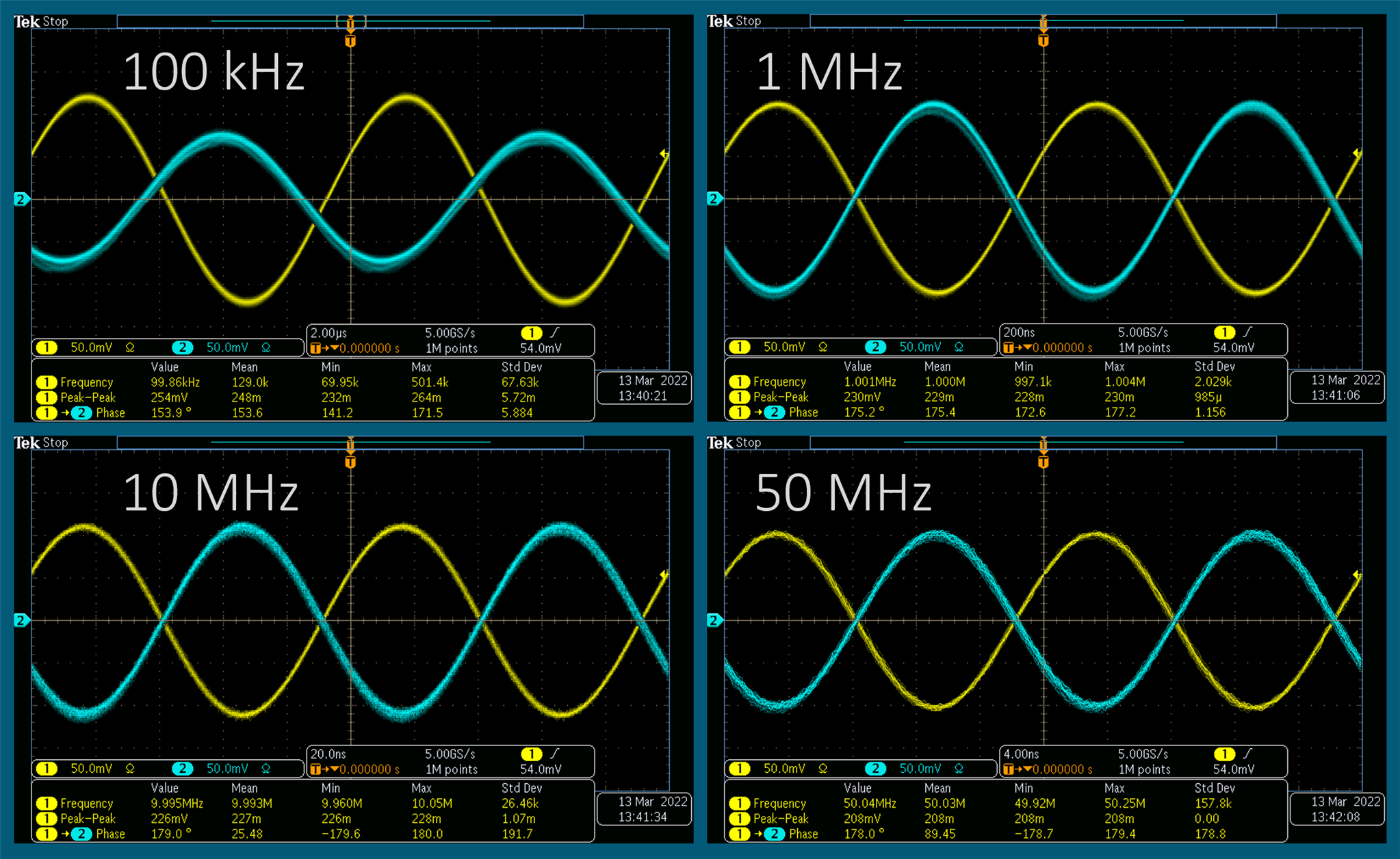
Here is the result; as can be seen, my implementation only works well from 1 MHz upward. I only tested to 50 MHz because that was the limit of the signal generator I was using (I could move to a different signal generator but this was just a first test).

image

Replicating the Project


If you wish to replicate this, the enameled wire was of 0.15 mm diameter, and two lengths of 30 cm were wound with about 10-12 twists per inch (i.e. one twist per 2-2.5mm), it's not critical, but try not to exceed that, and try to keep the wires touching throughout the twists, i.e. no gaps. The ferrite cores were Fair-Rite 5943000101  and I wound 18 turns, cut off the remainder, leaving 6 mm of wire, and then used a soldering iron and a blob of solder to burn off 2-3 mm of enamel off the ends. For the fourth ferrite, as mentioned, a third winding was added. That third wire was of the same length, wound around the twisted pair, but not with as much care, it just needs to ideally follow the same path. I didn't have 50-ohm through-hole resistors, so I used two 100 ohm resistors in parallel.


Other Ideas


I think wire-wrapping techniques could be a possibility for larger modules with wound components. For instance, here is an idea using a much larger core, and thicker wire – it was sanded on the ends prior to wire-wrapping with a WSU-30M wire-wrap tool . It's not a good idea to have tiny inductors on the ends : ) so the sanding needs to be fairly precise. Probably this method is better with coloured enamel, since then it is easier to see how much wire was sanded.

image

Summary


Pluggable modules can allow for more experimentation. I would not have liked to repeatedly solder/desolder tiny ferrite wound components, just to try out different topologies. Now, I can just re-wire the protoboard instead. The design could be improved with colored enameled wire (using this pack of 4 colors of enameled wire ), and also finding a way to secure the wound components mechanically (currently they are supported by the wire legs). To solve that, I'd like to perhaps investigate using UV-curing gel (it is used for securing nails apparently) at some point.

Thanks for reading!

  • Sign in to reply
  • jc2048
    jc2048 over 3 years ago

    Fair-Rite provide graphs of permeability against frequency for their cores, so I thought it might be interesting to see the difference between the type 43 material (NiZn) of your first core and the type 77 material (MnZn) of your second one.

    In case anyone is interested, here I've overlaid the 77 one (black) with the 43 one (red). I'm not wonderful with Gimp, but after a bit of fiddling around I managed to stretch the overlay to fit.

    image

    • Cancel
    • Vote Up 0 Vote Down
    • Sign in to reply
    • More
    • Cancel
  • shabaz
    shabaz over 3 years ago in reply to jc2048

    Hi Jon,

    The original ferrite core I tried was very small, hard to get many turns onto it, and fiddly. The 5977000201 is a bit larger (not much) but way easier to handle when winding, so I'd recommend that for experimenting. Type '43' are also very popular, especially for ham radio use, they are handy for baluns in the HF band. Any ferrite core available from ham radio places would also be good for experimenting.

    I've not tried fast pulses, I will be limited by things like the twisted transmission line not being as perfect as desired, plus the general assembly of the circuit, I used wire-ended resistors, and the wiring isn't as short as possible, but perhaps it may still work well to 100 MHz or more. In the low hundreds of MHz, perhaps the ferrite type I'm using begins to serve little purpose, so then I'd be relying on the number of turns having sufficient inductance as an (almost) air-core effectively. Although I did the calculation to know what inductance I was getting with the ferrite (just over 1.1 mH with that 5977000201 core), I didn't do it for an air-core with those number of turns.

    Incidentally, I still calculate the inductance, but recently discovered I don't need to, since there is a very good program that does it, called coil64. The screenshot below shows how to use it for the 5977000201 to work out turns for 1157 uH inductance. It's accurate (as accurate as it practically can be, since there can be perhaps 10% or so tolerance with ferrite, and I think it changes a lot with temperature too. Anyway, I've not found any error with the coild64 software, it seems to provide expected results.

    image

    Also, the other day I swapped around the oscilloscope and the signal generator, such that signals were fed in on the 0 deg and 180 deg connectors, and the 'scope was connected to I connected two signal generators to the same circuit, and this time the 'scope was connected to the connection labeled 'Input' on the schematic, and connected another 'scope channel to the remainder connection, and it was neat, I could see that by varying the phase between the two signals, either one or the other channel on the 'scope would go up or down in amplitude, as expected, but it's still nice to see it.. it's a fun circuit.


    • Cancel
    • Vote Up 0 Vote Down
    • Sign in to reply
    • More
    • Cancel
  • jc2048
    jc2048 over 3 years ago

    Interesting experiment. Thanks for blogging about it. I don't have any experience of such things at all (I'll have to buy some suitable ferrite cores and try it for myself). It's even a bit of a struggle getting my head around the theory. The role of the ferrite seems to be quite complicated, doing different things at low and high frequency, so it's nice to see a direct demonstration of how moving the transition between the low-frequency high-permittivity area to the higher frequency 'lossy' area with the two different ferrite materials affects the performance.

    Have you tried throwing fast pulses at it and seeing what emerges? If it's truly wideband it should preserve the pulse shape with reasonable fidelity.

    • Cancel
    • Vote Up 0 Vote Down
    • Sign in to reply
    • More
    • Cancel
  • shabaz
    shabaz over 3 years ago

    This fixed it : )

    image

    This is 35 turns of the red and green wire from that pack of 4 bobbins, wound on a different core. It is Fair-Rite 5977000201

    Using two of these in the same circuit as before, now I get these results; basically, it is now usable down to 50 kHz or so (with a few degrees phase error as can be seen in the mean phase automated measurement in the 'scope screenshot below; by about 100 kHz the error is down to a degree), but still functions well to 50 MHz and likely higher (I didn't test higher). 

    image

    • Cancel
    • Vote Up 0 Vote Down
    • Sign in to reply
    • More
    • Cancel
  • shabaz
    shabaz over 3 years ago

    The pack of 4 wires looks like this, they are basically sewing machine bobbins : ) 

    In terms of wire quantity alone it isn't worth the £10 cost, but for a small level of prototyping it's way better than spending £80+ for four larger reels. It's possible to wind a lot of ferrites with this small amount, I think there is 27 metres on each bobbin. 

    image

    • Cancel
    • Vote Up 0 Vote Down
    • Sign in to reply
    • More
    • Cancel
element14 Community

element14 is the first online community specifically for engineers. Connect with your peers and get expert answers to your questions.

  • Members
  • Learn
  • Technologies
  • Challenges & Projects
  • Products
  • Store
  • About Us
  • Feedback & Support
  • FAQs
  • Terms of Use
  • Privacy Policy
  • Legal and Copyright Notices
  • Sitemap
  • Cookies

An Avnet Company © 2025 Premier Farnell Limited. All Rights Reserved.

Premier Farnell Ltd, registered in England and Wales (no 00876412), registered office: Farnell House, Forge Lane, Leeds LS12 2NE.

ICP 备案号 10220084.

Follow element14

  • X
  • Facebook
  • linkedin
  • YouTube