Hi all!
There is no such "superior prototype technique" for circuits. Every project has its unique caracteristics and that imply different prototyping technniques. Down below I will present my experiences, what techniques I use the most, what I don't use that often and what I like the most. Feel free to comment and share your experience!
Pen and paper
No, I'm not suggesting you to grab some conductive ink and connect components by drawing traces on a piece of paper (altough you could do so if you want ). I'm talking about sketches, block diagrams or simply writing down whatever you want to create.
Personally I never skip this step, even for the simpler project. Even a simple drawing on a 5cm by 5cm paper offcut, but I always put on paper what I want to create.
Why is that so important? Conveing ideas into something that is not volatile allow me to better imagine, organize and implement what I'm planning to create. Without that, I would probably need a bigger bucket for failed projects and quite a bit of air freshener to cover the "magic smoke" smell .
That is why, for me, planning ahead on a piece of paper is the most valuable tool at my disposal. And it's also cheap!
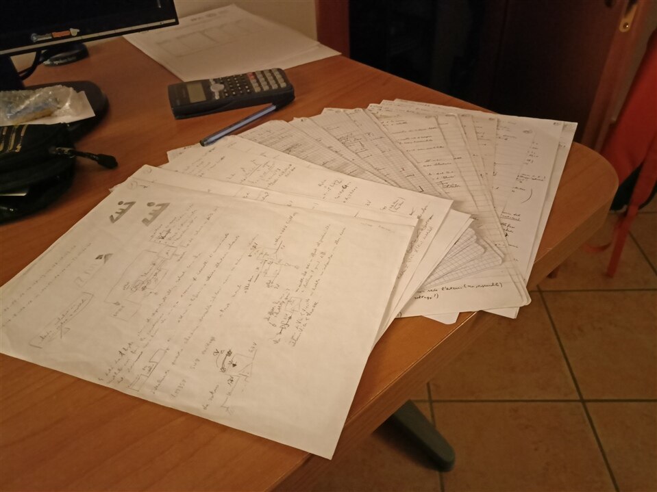
30 pages of reasoning and learning just for a single project!
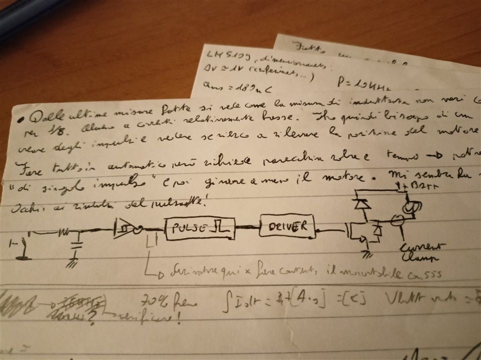
One of many block diagrams.
Breadboards
Another easy way to test a circuit is to built it on a breadboard. It can't be easier than this: just grab components, push them into the breadboard and add connections with a solid core wire.
However, I don't use breadboards very often to build complete circuits for two main reasons:I have only two relatively small breadboards (so I'm space limited) and also connecting a lot of components one to another can become a bit messy if wiring isn't managed correctly. What I actually like to do is to to test, when possible, smaller sub circuits using breadboards. By doing so I can keep complexity low while troubleshooting in a time efficient way any possible problem.
Following the same logic, I've also used them as temporary "mod board": just bring out needed signals from your pcb (or microcontroller evaluation board!) to an external breadboard, add additional circuit and then feed back the signal on the "main" board. If it works on a breadboard, the additional circuitry will work for sure once integrated on a single pcb .
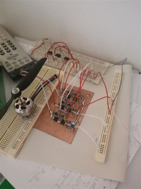
This is quite an old photo, but it shows well how I like to use breadboards to test sub circuits in conjunction with other PCBs
Perfboards
Perfboard (perforated boards, prototype board, call them how you prefer ) to me are an happy middleground to obtain a working circuit that could be moved, used and carried around without the fear of losing camponents because they unclip from the breadboard (it's rare, but I have some buttons that really like to pop free from my breadboards). It's also a more reliable way to building a circuit if you need any kind of high current capability.
Perfboards exist in many different kinds: you can find ones with array of single pads , with premade connections bars, with the same connection layout of a breadboard and so on. My absolute favourites are boards with pads isolated one to another, simply because to me are the most flexible ones: I can just keep on hand a few of them and I can arrange a circuit as I need without the limitation of pre made connections.
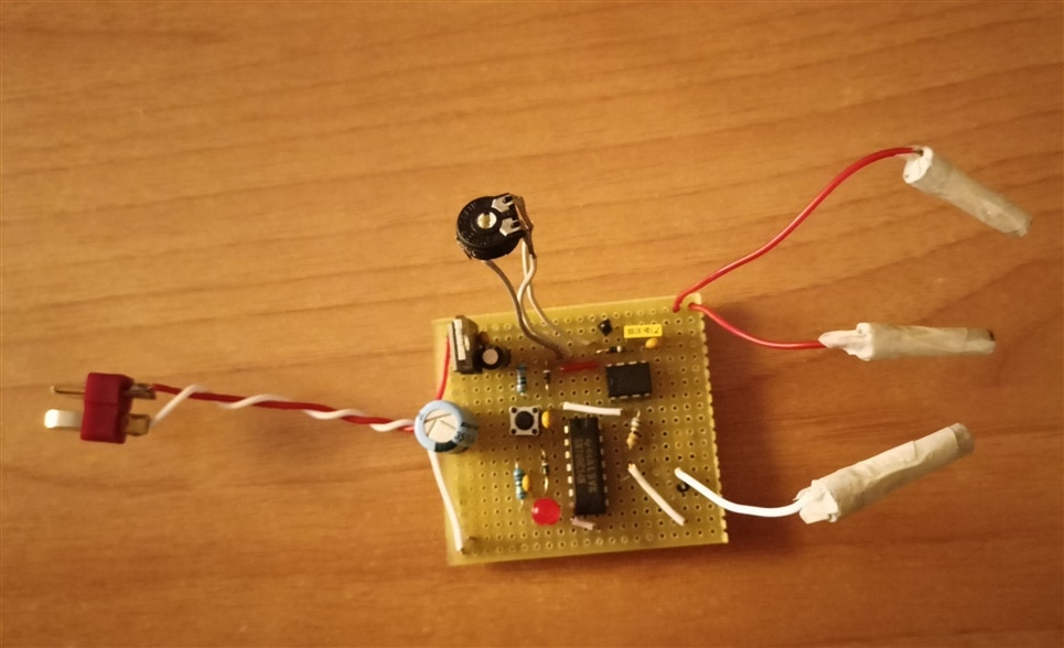
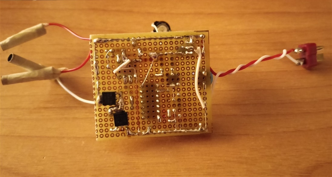
Example of a circuit made using perfboard: pulse generator to measure inductance of a motor
DIY PCBs
One step further from perfboards are actual dyi PCBs. Usually manufacturing can be divided into two categories: mechanical milling and chemical etching. Personally I like (and use) the first option simply because it's less messy and I don't have to manage and properly dispose chemical solutions.
Milling PCBs comes with it's own set of challenges, expecially when done using a self made router, but good results are still achievable. Tracks down to 0.5mm can be done with a bit of patience and machine tuning.
The main downside of this method, compared to a "real" PCB is the absence of plated vias. Trust me, soldering a small piece of wire through all vias to connect traces on opposite sides is quite a tedious task!
On the other side, if you are in a hurry you can built your own PCB in manner of hours and don't wait for manufacturing/shipping times.
Doing PCB from myself also allowed me to appreciate the technology and the work that is usually hidden when ordering PCB from a professional manufacturer. Learning, even at small scale, to deal with process and technology limitations (basically, limitation of my router in my specific case) to me has been quite beneficial.
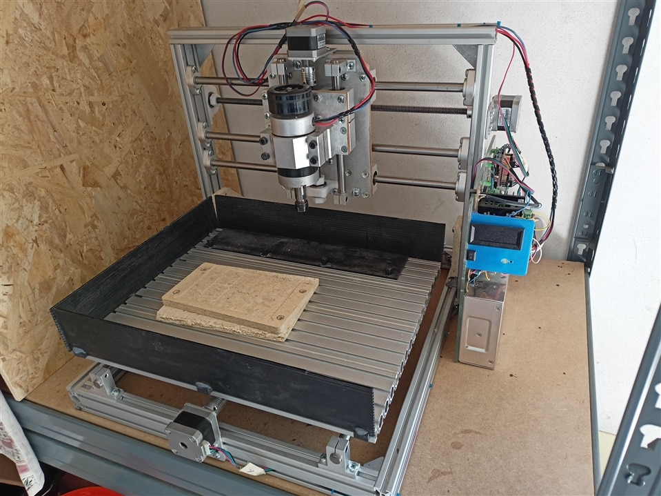
My homemade milling machine to mill PCBs.
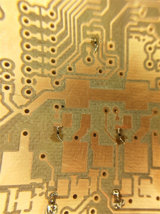
Milled PCB example. Soldered resistors are 0402!
Professionally made PCBs
I have to admit that, as hobbist, I've never ordered PCBs, at least yet! My experience here is "limited" to what I've seen/used at work.
Premade PCBs are very handy and easy to handle/assemble compared to all previously mentioned method, no surprise here. At home I start thinking about profesionally made PCBs when my manufacturing capabilities are not up to the requirements. In the end, to me these are just a tool as every other technique described above. I use it if I really need it, and I use the tool that better fit my requirements time to time.
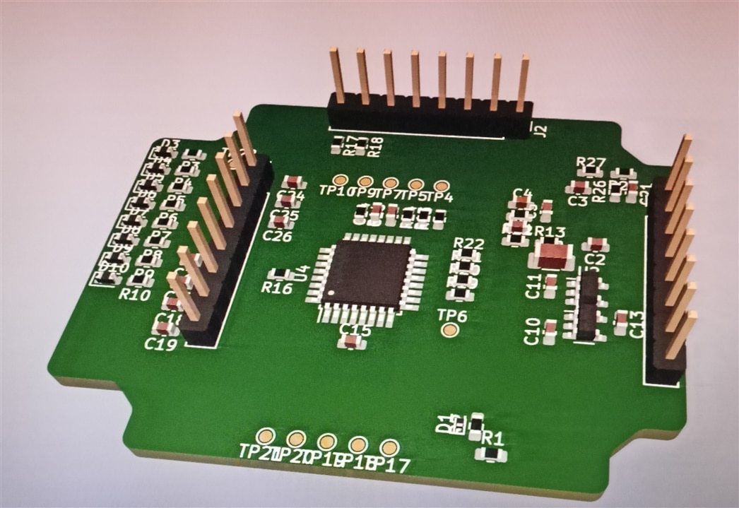
PCB work in progress
Other experiences
Altough I've not used extensively, in the past I've done a couple of circuits using wire wrap, mainly at school. Probably back then the main prototiping technique in the lab was simply bodging all toghether hoping for the best
All these "techniques" into one project
The project I'm working on (BLDC sensorless controller for an RC car) has seen some up and down, but thank to its longevity I've used all described techniques to develop prototypes and to learn along the way.
As a final touch, a video of a drone motor spinning and starting up without hesitations (common in sensorless systems) and another comparison video with my actual RC car (which is not bad at all!).
Final boards hopefully coming soon!
Video #1: start up procedure on my RC car. The motor (sensorless) has a small hesitation.
Video #2: motor start up with my prototype.
