This blog is a continuation from Part 1.
What's cooking with that reflow oven of yours (part 1)
Let the experimentation begin
This is the really messy part of the development process. Here I evaluated different elements that make up the project and tested out some ideas for improvement.
Insulating to reduce energy/heat loss
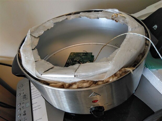
My first hack of the day was to improve the heat retention as I wanted to be able to maintain a temperature with little or no energy input for the reflow "soak zone" and to reduce energy/heat losses. After a bit of hunting around I found that glass or rock wool insulation could withstand high enough temperatures so I grabbed some glass wool insulation from the attic and stuffed it in between the inner and outer shell of the slow cooker. I also added in some fibreglass fabric or ribbon for good measure, but I think that was a bit of overkill.
I also cut away and folded in the inner shell to separate it from the outshell. This also acted as a shelf for the halogen flood light. It may not look pretty, but it works. In fact, the irregular surface is beneficial to allow a some heat to escape.
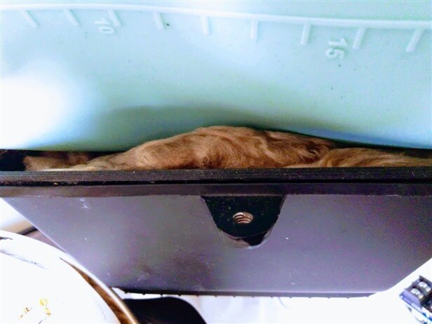
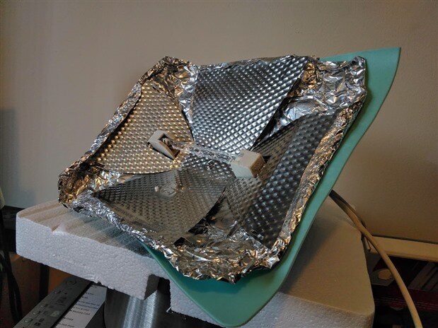
I also wanted to insulate the halogen die cast aluminium casing to reduce energy/heat loss and, more importantly, to prevent burning if I accidentally touched the outer casing. So for the second hack of the day, I took the wall mounting bracket, which was attached to the floodlight body, and screwed this inside the die cast body to allow me to move the R7 lamp holder forward. I then was able to fill the air gap with glass wool insulation and then I placed a silicon baking mat, which is also good at withstanding high temperatures, between the glass wool and the dimpled anodised aluminium reflector shield. This also allowed the reflector shield to be made flatter with the help of some aluminium tin foil, which then also allowed the flood light to rest on top of the slow cooker.
| {gallery:autoplay=false} My Gallery Title |
|---|
Using a Solid State relay (SSR) for Halogen Lamp control
I was heavily influenced by the feedback received for the fan heater when I had posted a question on Element14 website about remote heat control and had made a purchase online to get one of these SSR's.
The device I purchased was a FOTEK 40A relay which accepts a 3-32V DC input.
The FOTEK datasheet offers two control methods:
For my experimentations I used the Zero Crossing Trigger method. This was really just to see how well or not so well this method worked. Well I can confirm that it does not work that well. So, that's one learning exercise ticked off (as in see for myself what this does). I ran out of time testing the Variable Resistance Control method. So in the demo video you will see the halogen lamp blinking rather than dimming.
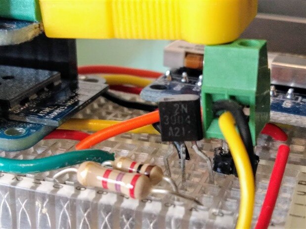
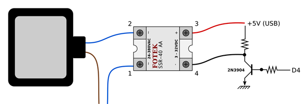
For the controller circuit, I used an NPN transistor and configured the SSR to act as a NO device:
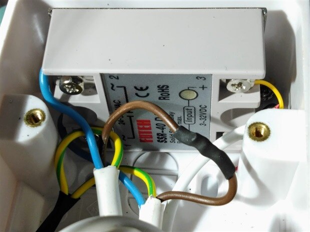
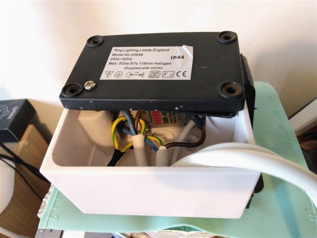
I then inserted the SSR into a junction box which conveniently was the right size I needed.
| {gallery:autoplay=false} My Gallery Title |
|---|
 |
Some prelim testing to develop some heating profile control logic
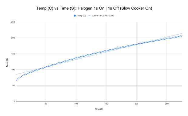
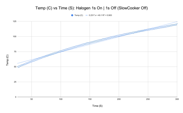
I was always curious to understand what impact does the slow cooker high power setting have on the overall temperature profile. Here is a test using a 1 second halogen lamp pulse (i.e. 1 second on and 1 second off):
| {gallery:autoplay=false} Temperature Profiles (with Slow Cooker on or off) |
|---|
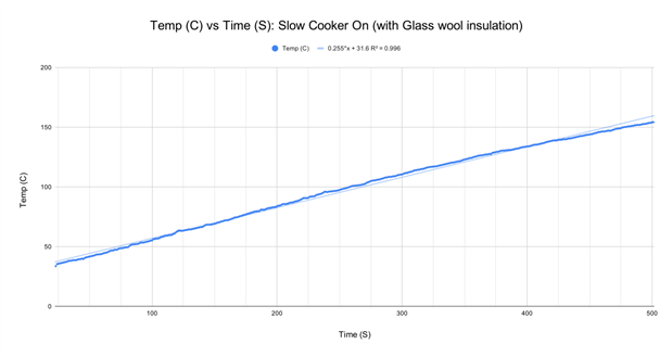 |
Just with that simple pulse pattern there was a difference in the temperature gradient achieved depending on whether the slow cooker was switched on (high setting) or switched off. With the slow cooker switched on we were able to achieve a 0.47 degree temperature increase per second while if the slow cooker was switched off we could only achieve a 0.25 degree per second increase. Interestingly pulsing the Halogen light every 1 second is equivalent to just having the slow cooker on (with the glass wool insulation) as it achieve a similar temperature gradient.
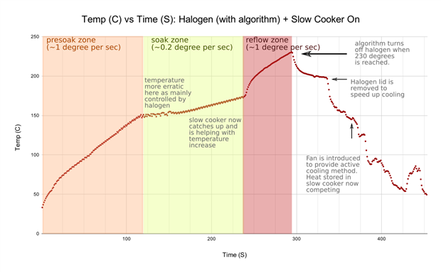
I then played around with the timings for the Halogen lamp on-off cycle to ensure that I could control my temperature gradients to suit a typical reflow pattern. This was all threshold driven, for now, where the on-off cycle changed depending on the temperature reached and what zone I was in (i.e. preheat, soak or reflow).
This is not how a control system should operate but, in my view, this is the first step you should undertake, i.e. complete a significant number of controlled tests, in order to determine the behaviour of your system before developing your controller algorithms. Only once you have the temperature behaviour data, can you establish a feedback loop system which automatically responds to the actual temperature gradient.
So, after a bit of experimentation here is the resulting temperature profile created when the halogen on/off cycle algorithm is based on temperature thresholds. This is demonstrated in the video.
Here is the new Arduino function, which was added to the code for heat control:
void ControlSSR()
{
  if (Tval >= 30 && RCval != 4) {
    if (Tval < 55) {
      // On for 500ms and off for 500ms
      if (SSRstate) {
        SSRstate = LOW;
        digitalWrite(SSR, SSRstate);
      }
      else {
          SSRstate = HIGH;
          digitalWrite(SSR, SSRstate);
      }
    }
    else if (Tval < 100.5) {
      // On for 1000ms and off for 500ms
      if (SSRstate) {
        if (SSRintCnt) {
          SSRstate = LOW;
          digitalWrite(SSR, SSRstate);
          SSRintCnt = 0;
        }
        else {
          SSRintCnt++;
        }
      }
      else {
          SSRstate = HIGH;
          digitalWrite(SSR, SSRstate);
      }
    }
    else if (Tval < 125.5) {
      // On for 1500ms and off for 500ms
      if (SSRstate) {
        if (SSRintCnt>1) {
          SSRstate = LOW;
          digitalWrite(SSR, SSRstate);
          SSRintCnt = 0;
        }
        else {
          SSRintCnt++;
        }
      }
      else {
          SSRstate = HIGH;
          digitalWrite(SSR, SSRstate);
      }
    }
    else if (Tval < 150.5) {
      // On for 2000ms and off for 500ms
      if (SSRstate) {
        if (SSRintCnt>2) {
          SSRstate = LOW;
          digitalWrite(SSR, SSRstate);
          SSRintCnt = 0;
        }
        else {
          SSRintCnt++;
        }
      }
      else {
          SSRstate = HIGH;
          digitalWrite(SSR, SSRstate);
      }
    }
    else if (Tval < 174.5) {
      // On for 500ms and off for 1000ms
      if (!SSRstate) {
        if (SSRintCnt) {
          SSRstate = HIGH;
          digitalWrite(SSR, SSRstate);
          SSRintCnt = 0;
        }
        else {
          SSRintCnt++;
        }
      }
      else {
          SSRstate = LOW;
          digitalWrite(SSR, SSRstate);
      }

    }
    else if (Tval < 230) {
      // On permanently
      if (!SSRstate) {
        SSRstate = HIGH;
        digitalWrite(SSR, SSRstate);
      }
    }
    else {
      RCval = 4;
      // Update the TFT screen
      tft.fillRect(5, 35, 120, 25, BLACK);
      tft.setTextColor(CYAN);
      tft.print("COOLING");

      // We turn off the SSR driven heat source
      if (SSRstate) {
        SSRstate = LOW;
        digitalWrite(SSR, SSRstate);
      }
    }
  }
  else {
    if (RCval == 4) {
      // We turn off the SSR driven heat source
      if (SSRstate) {
        SSRstate = LOW;
        digitalWrite(SSR, SSRstate);
      }
    }
  }
}
And here's the demo
The processing code to produce the graphical output and log the data is here:
/* Processing code for this example */

  // Graphing sketch

  // This program takes ASCII-encoded strings from the serial port at 115200 baud
  // and graphs them. It expects 2 comma separated variables (time and temperature), followed by a
  // newline and carriage return

  // created 20 Apr 2005
  // updated 24 Nov 2015
  // by Tom Igoe (this example was modified by BigG: October 2020)
  // This example code is in the public domain.

  import processing.serial.*;

  Serial myPort;        // The serial port
  PrintWriter LogOutput;

  int xPos = 1;         // horizontal position of the graph
  int inByte = 0;

  void setup () {
    // set the window size:
    size(1200, 400);
    frameRate(2);    // Updates the graphical output at 2 frames per second

    // List all the available serial ports
    // if using Processing 2.1 or later, use Serial.printArray()
    //printArray(Serial.list());

    // I know that the first port in the serial list on my Mac is always my
    // Arduino, so I open Serial.list()[0].
    // Open whatever port is the one you're using.
    myPort = new Serial(this, Serial.list()[0], 115200);

    // don't generate a serialEvent() unless you get a newline character:
    myPort.bufferUntil('\n');

    // Create a new file in the sketch directory
    LogOutput = createWriter("ReflowTemp.csv");

    // set initial background:
    background(0);
  }

  void draw () {
    // draw the line:
    stroke(127, 34, 255);
    line(xPos, height, xPos, height - inByte);

    // at the edge of the screen, go back to the beginning:
    if (xPos >= width) {
      xPos = 0;
      background(0);
    } else {
      // increment the horizontal position:
      xPos++;
    }
  }

  void keyPressed() {
    LogOutput.flush(); // Writes the remaining data to the file
    LogOutput.close(); // Finishes the file
    exit(); // Stops the program
  }


  void serialEvent (Serial myPort) {
    // get the ASCII string:
    String inString = myPort.readStringUntil('\r');

    if (inString != null) {
      // trim off any whitespace:
      inString = trim(inString);
      int c1 = inString.indexOf(",");
      if (c1 >=0) {
        inByte = int(inString.substring(c1+1));
      }
      else inByte = -1;
      // convert to an int and map to the screen height:
      println(inString);
      LogOutput.println(inString);
    }
  }
Closing remarks
This project was more about developing a suitable control system for my halogen lamp than demonstrating that I could match a prescribed reflow heating profile for a specific solder paste. That will come. For now it is about finding balance between energy input for the heating up phase and then, as I have discovered, having sufficient heat loss for controlled cooling. That is some way off but I feel I now have all the elements in place to continue the refinement process. At least I know that you can achieve the desired temperatures for reflow, although temperature gradients are probably on the conservative side, using just a 230W halogen light bulb and a 170W slow cooker.
This project has been a great journey of discovery.


Top Comments
-

DAB
-
Cancel
-
Vote Up
+1
Vote Down
-
-
Sign in to reply
-
More
-
Cancel
Comment-

DAB
-
Cancel
-
Vote Up
+1
Vote Down
-
-
Sign in to reply
-
More
-
Cancel
Children