My automation project has provided some challenges. I’m continuing to work at it, but I needed some design changes to accomplish raising and lowering the bridge automatically without failures.
It has been a while since the challenge was kicked off and an equal amount of time since I made my post. I am working to completing the project before the end of May. Other retirement stuff is taking up my time.

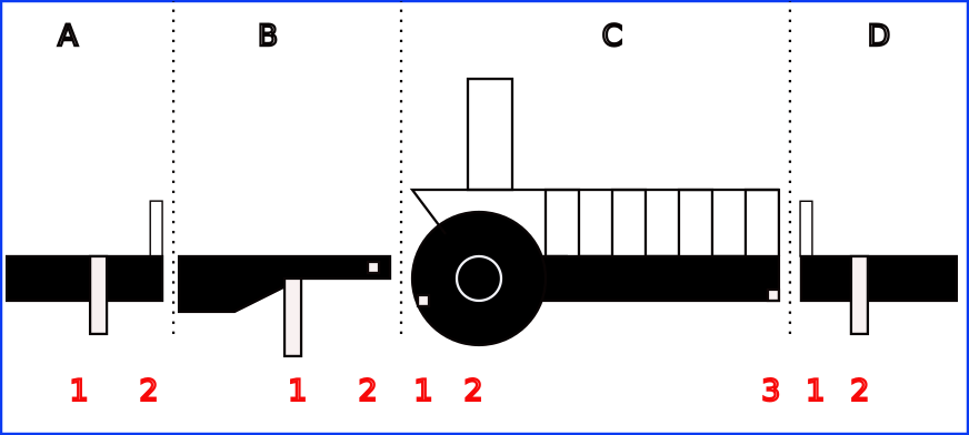
The current design divides the layout into four areas A, B, C, & D. The letter designation reference the island side area, B the ramp area, C the bridge area and D mainland side area for descriptions.
Each area has sensors and/or animation devices (i.e. motors, light and sound) referenced by the numbers.
A1: is a magnetic attached to a servomotor. Raising the magnetic stops the vehicle at the approach. The magnet triggers a reed switch in the vehicle to kill power.
A2: is a barrier raised and lowered by a servo.
B1: has a servo that raises and lowers the ramp.
B2: is a magnetic sensor triggered by an earth magnet attached to the ramp to detect if the ramp is up or down.
C1: is an IR sensor to stop the bridge on maximum rise.
C2: is a geared DC motor to raise and lower the bridge (the bride has left the building:))
C3: a magnetic sensor triggered by an earth magnet attached to the bridge to detect if the bridge is up or down.
D1: barrier on mainland side of bridge.
D2: vehicle stop magnet on mainland side of bridge.
My original plan was to use on one Arduino to animate the scenario of sound alarm with lights, lower the barriers, stop the bus, raise the ramp and raise the bridge. Then reverse the scenario. I have since added an Arduino dedicated to managing sensor readings and bridge movement.
I discovered during motor testing to raise and lower the bridge there are many things can go wrong. When little humans (i.e children) are involved a lot more can go wrong. Wrong would cause damage to the structures. To prevent things from going wrong, I added some sensors. The sensors provide feedback to establish logic that can control the bridge's action.
Given sufficient resources, I feel the complete animation could be done with one Arduino. Using Nano’s (i.e. what I have on hand) I have limited I/O pins. Added the additional Nano provided more I/O.
The extra Nano enabled me to divide the animation between two microcontroller devices. One controller is now responsible for the bridge motor guided by sensor readings, the other can look after the servos and playing sound.
I just completed the sensor installs. The other animation devices are in place and working. I have a scenario coding to raise and lower the bridge with the bridge coding section absent. I’ve just started work on coding the bridge up and down sequence. Hopefully without a catastrophic failure.
