


This is project AquaLoop, design of 4-20mA current loop based water level indicator for all sized water tanks. The main target is to make the system robust, low noise, less lossy over a distance for signal transmission. I am using a BC547 based water level indicator circuit, OPA211 Op-Amp for signal conditioning, UA741 Op-Amp with BC557 as a current transmitter, LM393 comparators for driving the bar LEDs and an R2R ladder network for signal conditioning. No microcontroller, No coding, All analog and data conversion.
The Problem
The solution comes from the problem, the problem comes from life and project is made for the solution.
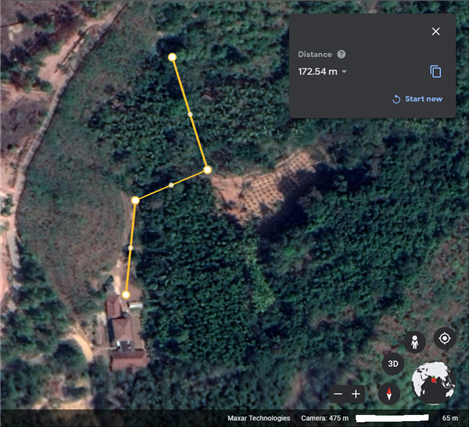
This is the distance between my home to the irrigation water tank. So, what? There is a problem!
The water level in this tank must be frequently checked to on/off valves for irrigation. This is being done manually every time by going there and peeking into the tank. Some time ago, I tried to implement a transistor-based water level indicator for this tank with status LEDs but, that didn't work well because of bad visibility due to proximity. Then, tried pulling the wires long towards home but, there were 4 pairs of them for LEDs and also power lossy for that battery-powered device.
Recently, I came across the 4-20 milliampere current loop technology which comes way back from the 1950s prominently used in industries for machinery control. Went through few docs and app notes. So,.....4-20mA current loop seems cool and thought of implementing it for this application.
What is a 4-20mA current loop anyhow?
https://www.predig.com/indicatorpage/back-basics-fundamentals-4-20-ma-current-loops
https://www.youtube.com/watch?v=Qyl_dvbgG2Y
The Plan
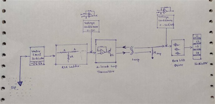
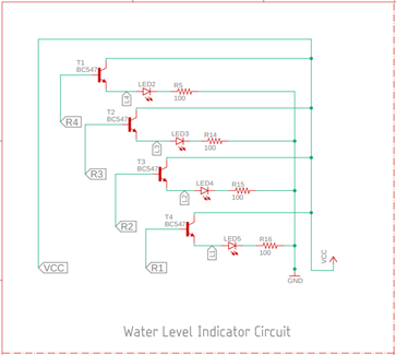
The system is divided into 5 blocks with the water level indicator being the first one for getting digital reading based on the level as sensed by the transistor. If Vcc is let to the water(5V), with common emitter(CE) configuration, dipping the transistor base terminal to the same would pick up a minute amount of current and we have β times amplification so as to drive the LED. Multiple water levels are monitored using this method.
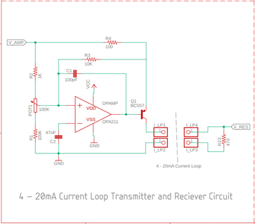
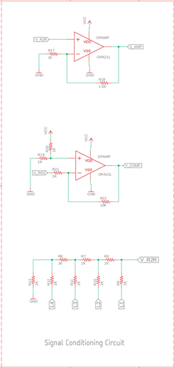
Next comes the R2R ladder based digital to analog converter(DAC) which takes in the water level data from 4 transistors and converts to equivalent analog voltage in 0-5V range. Hence, this analog voltage also fluently determines the same water level value. This is done to condition the 4-20mA transmitter circuit and to provide equivalent current to the loop using the Op-Amp which drives the base of current transmitting BJT.
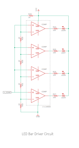
On another side of the loop, a resistor is placed whose value is predicted based on the range of voltage required to measure for the receiver. It's nothing but the voltage across the resistor is measured and that is a function of the level of the water as encoded in the current. The consequence of Ohm's law is that the voltage across a resistor is equal to current times resistance helps here. This acquired voltage is fed to the bar LED driver which is an LM393 comparator based circuit to show the appropriate level of water, visually digitally using LEDs. Overall it's a Digital - Analog - Digital conversion (LoL......DAD).
Schematics
Time for schematics,.......structuring and giving life to the plan. I used Eagle PCB software to design these.
Testing and Working
Now, doing some preliminary testing to validate the design. I used UA741 Op-Amp initially(moved to OPA211 rail to rail opamp later) to check test the current loop. Found that it was giving a lot of distortion and output voltage has saturated early(not with the scope though). What I am designing is not a standard 4-20mA current loop as it's not driven by 24V and strictly adhered to 4-20mA signals, but closer or a mimic of it with some limitations.
Being done with comparator setup for driving bar LEDs, I tested it by tuning 0 to 5V using a variable buck convertor. That looked fine and the only thing was to have exact 0 to 5V for this comparator setup to switch and drive LEDs.
After testing and tweaking a few resistive feedback and offset parameters, I integrated all the sections. Below is the image of full setup highlighted block by block.

Yes, there is a LED in the middle which isn't functional and I was nearly able to get the full-scale range of the actual water level which is in 4-bits(4 LEDs). This is how it works, with LEDs behind showing water level directly from the transistor signal and the bar LED showing the same corresponding water level through a long way of 4-20mA current loop.
Conclusion
I have used 4-20mA loop for water level monitoring application, but this also can be extended for various sensor and DAQ system applications. It's just that we can encode the sensor signal into current and decode on the other side without significant losses. I loved making this and was an amazing experience to play with some data conversion and signalling circuitry. Going full-stack analog,.....
The one thing which I understood(maybe lately) is that analog stuffs aren't easy, yet not hard if making process is enjoyed. It took me way longer than expected to test + make this and there are a lot of culprits coming into the design like offsets, noise, distortion, instability over time and what not? Its all crap without doing some math and calculations to understand circuit parameters. And finally, it works and should work!
Do let me know your views on this and any improvement/upgrade plans for this project. Thanks 
Links and References |
|---|
|
https://www.bapihvac.com/application_note/the-science-of-4-to-20-ma-current-loops-application-note/ |
| W2AEW's practical opamp signal conditioning https://youtu.be/OlhN7ADpKds |
| Loop-powered 4- to 20-mA transmitter circuit https://www.ti.com/lit/an/slaa866/slaa866.pdf |
| Making a Tiny 4-20mA Current Loop Tester https://www.youtube.com/watch?v=68JOFEr4AWg |
| NPTEL Lec-23 on 4-20 mA current Transmitter design https://www.youtube.com/watch?v=7jwzkMvfbbU |
| 0-5V or 4-20mA to 0-5V signal converter https://www.electronicsworld.co.uk/wp-content/uploads/2019/04/2019ewApr-1.pdf |