


Hello Everyone, My name is Harji Nagi.I am currently third year student studying electronics and communication engineering in India. I have a keen interest in robotics, analog, digital electronics and embedded system.
Step 1: Introduction
I made a smart "Calorie Meter and Activity Tracker" via Arduino Nano , HC-05 Bluetooth Module and MPU-6050MPU-6050 which is a perfect combination of 3-axis accelerometer and 3-axis gyroscope.It is implemented by Arduino has only one feature, which is collecting data by using accelerometer and sending them to a mobile device. Then the mobile device calculates the calories and steps by using the data. The feature is simple, and that means the structure of this device is way simpler than RetroWatch, so it’s very easy to make it in your own taste.
The android app(Retro Band) check steps using collected data provided from Arduino. The algorithm of the app is not that complicated. If you have much experience to this area, you can replace it with your own algorithm. The app saves the calorie data, so you can see the progress it in a monthly/daily/hourly graph form. Arduino cannot save the data itself since the shortage of its memory capacity. That is, it only works when it’s connected with a mobile device, which means you cannot collect the data with Arduino only.
The Component list are:
1)Arduino Nano
2)HC-05 Bluetooth Module
3)MPU-6050
4)Voltage Regulator 3.3V
5)Ceramic Capacitor 100nf
6)Electrolytic Decoupling Capacitor 10uf/25V
7)Lithium Polymer Battery 7.4V
8)Some Male to Male Jumper Wires
The MPU-6050MPU-6050 is the motion tracking device designed for the low power, low cost and high performance. .The MPU-6050MPU-6050 send its data via Hc-05 Bluetooth module to your connected mobile devices.
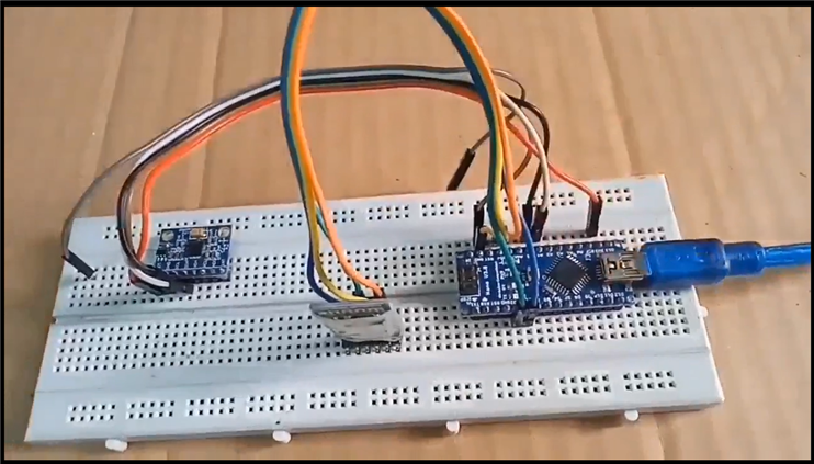
Step 2: Connection

Connecting Arduino-Bluetooth module
Connect VCC, GND, TXD, RXD pin as the module in the instruction (VCC->3.3v, GND->GND, TX->D2, RX->D3).
Connecting Arduino-Accelerometer(MPU-6050)
An accelerometer module uses I2C interface. (VCC->3.3v, GND->GND, SDA->A4, SCL->A5)
Connecting Arduino – battery
It’s very simple to supply the power. Just connect  -> RAW with
  -> GND. But if you care about recharging, you can use a Li-Po recharging module. In this case, you should connect and connectors on the battery with B+,B- on the recharging module, and out+, out- on the module should be connected with RAW, GND on the Arduino board respectively. In this project ,I used power bank to power up the Arduino.
Step 3: Code
You are done with the connections now.
Before uploading the code you would require to download 3 libraries.
1. https://www.i2cdevlib.com/usage
2. https://playground.arduino.cc/Main/MPU-6050
3.https://github.com/PaulStoffregen/SoftwareSerial/archive/master.ziphttp://
Upload the code after doing the required connections.
#include <math.h>
#include <Wire.h>
#include <SoftwareSerial.h>
/* Bluetooth */

SoftwareSerial BTSerial(2, 3); //Connect HC-06. Use your (TX, RX) settings


/* time */

#define SENDING_INTERVAL 1000

#define SENSOR_READ_INTERVAL 50

unsigned long prevSensoredTime = 0;

unsigned long curSensoredTime = 0;


/* Data buffer */

#define ACCEL_BUFFER_COUNT 125

byte aAccelBuffer[ACCEL_BUFFER_COUNT];

int iAccelIndex = 2;


/* MPU-6050 sensor */

#define MPU6050_ACCEL_XOUT_H 0x3B // R

#define MPU6050_PWR_MGMT_1 0x6B // R/W

#define MPU6050_PWR_MGMT_2 0x6C // R/W

#define MPU6050_WHO_AM_I 0x75 // R

#define MPU6050_I2C_ADDRESS 0x68


typedef union accel_t_gyro_union {

struct {

uint8_t x_accel_h;

uint8_t x_accel_l;

uint8_t y_accel_h;

uint8_t y_accel_l;

uint8_t z_accel_h;

uint8_t z_accel_l;

uint8_t t_h;

uint8_t t_l;

uint8_t x_gyro_h;

uint8_t x_gyro_l;

uint8_t y_gyro_h;

uint8_t y_gyro_l;

uint8_t z_gyro_h;

uint8_t z_gyro_l;

} reg;


struct {

int x_accel;

int y_accel;

int z_accel;

int temperature;

int x_gyro;

int y_gyro;

int z_gyro;

} value;

};


void setup() {

int error;

uint8_t c;


Serial.begin(9600);

Wire.begin();

BTSerial.begin(9600);  // set the data rate for the BT port


// default at power-up:

// Gyro at 250 degrees second

// Acceleration at 2g

// Clock source at internal 8MHz

// The device is in sleep mode.

//

error = MPU6050_read (MPU6050_WHO_AM_I, &c, 1);

Serial.print(F("WHO_AM_I : "));

Serial.print(c,HEX);

Serial.print(F(", error = "));

Serial.println(error,DEC);


// According to the datasheet, the 'sleep' bit

// should read a '1'. But I read a '0'.

// That bit has to be cleared, since the sensor

// is in sleep mode at power-up. Even if the

// bit reads '0'.

error = MPU6050_read (MPU6050_PWR_MGMT_2, &c, 1);

Serial.print(F("PWR_MGMT_2 : "));

Serial.print(c,HEX);

Serial.print(F(", error = "));

Serial.println(error,DEC);


// Clear the 'sleep' bit to start the sensor.

MPU6050_write_reg (MPU6050_PWR_MGMT_1, 0);


initBuffer();

}


void loop() {

  curSensoredTime = millis();


  // Read from sensor

  if(curSensoredTime - prevSensoredTime > SENSOR_READ_INTERVAL) {

   readFromSensor();  // Read from sensor

  prevSensoredTime = curSensoredTime;


   // Send buffer data to remote

   if(iAccelIndex >= ACCEL_BUFFER_COUNT - 3) {

   sendToRemote();

   initBuffer();

  Serial.println("------------- Send 20 accel data to remote");

  }

  }

}


/**************************************************

 * BT Transaction

 **************************************************/

void sendToRemote() {

  // Write gabage bytes

  BTSerial.write( "accel" );

  // Write accel data

  BTSerial.write( (char*)aAccelBuffer );

  // Flush buffer

  //BTSerial.flush();

}


/**************************************************

 * Read data from sensor and save it

 **************************************************/

void readFromSensor() {

  int error;

  double dT;

  accel_t_gyro_union accel_t_gyro;


  error = MPU6050_read (MPU6050_ACCEL_XOUT_H, (uint8_t *) &accel_t_gyro, sizeof(accel_t_gyro));

  if(error != 0) {

  Serial.print(F("Read accel, temp and gyro, error = "));

  Serial.println(error,DEC);

  }


  // Swap all high and low bytes.

  // After this, the registers values are swapped,

  // so the structure name like x_accel_l does no

  // longer contain the lower byte.

  uint8_t swap;

  #define SWAP(x,y) swap = x; x = y; y = swap

  SWAP (accel_t_gyro.reg.x_accel_h, accel_t_gyro.reg.x_accel_l);

  SWAP (accel_t_gyro.reg.y_accel_h, accel_t_gyro.reg.y_accel_l);

  SWAP (accel_t_gyro.reg.z_accel_h, accel_t_gyro.reg.z_accel_l);

  SWAP (accel_t_gyro.reg.t_h, accel_t_gyro.reg.t_l);

  SWAP (accel_t_gyro.reg.x_gyro_h, accel_t_gyro.reg.x_gyro_l);

  SWAP (accel_t_gyro.reg.y_gyro_h, accel_t_gyro.reg.y_gyro_l);

  SWAP (accel_t_gyro.reg.z_gyro_h, accel_t_gyro.reg.z_gyro_l);


  // Print the raw acceleration values

  Serial.print(F("accel x,y,z: "));

  Serial.print(accel_t_gyro.value.x_accel, DEC);

  Serial.print(F(", "));

  Serial.print(accel_t_gyro.value.y_accel, DEC);

  Serial.print(F(", "));

  Serial.print(accel_t_gyro.value.z_accel, DEC);

  Serial.print(F(", at "));

  Serial.print(iAccelIndex);

  Serial.println(F(""));


  if(iAccelIndex < ACCEL_BUFFER_COUNT && iAccelIndex > 1) {

   int tempX = accel_t_gyro.value.x_accel;

   int tempY = accel_t_gyro.value.y_accel;

   int tempZ = accel_t_gyro.value.z_accel;

   /*

  // Check min, max value

  if(tempX > 16380) tempX = 16380;

  if(tempY > 16380) tempY = 16380;

  if(tempZ > 16380) tempZ = 16380;


  if(tempX < -16380) tempX = -16380;

  if(tempY < -16380) tempY = -16380;

  if(tempZ < -16380) tempZ = -16380;


  // We dont use negative value

  tempX += 16380;

  tempY += 16380;

  tempZ += 16380;

   */

   char temp = (char)(tempX >> 8);

   if(temp == 0x00)

  temp = 0x7f;

  aAccelBuffer[iAccelIndex] = temp;

  iAccelIndex++;

  temp = (char)(tempX);

   if(temp == 0x00)

  temp = 0x01;

  aAccelBuffer[iAccelIndex] = temp;

  iAccelIndex++;


  temp = (char)(tempY >> 8);

   if(temp == 0x00)

  temp = 0x7f;

  aAccelBuffer[iAccelIndex] = temp;

  iAccelIndex++;

  temp = (char)(tempY);

   if(temp == 0x00)

  temp = 0x01;

  aAccelBuffer[iAccelIndex] = temp;

  iAccelIndex++;


  temp = (char)(tempZ >> 8);

   if(temp == 0x00)

  temp = 0x7f;

  aAccelBuffer[iAccelIndex] = temp;

  iAccelIndex++;

  temp = (char)(tempZ);

   if(temp == 0x00)

  temp = 0x01;

  aAccelBuffer[iAccelIndex] = temp;

  iAccelIndex++;

  }


  // The temperature sensor is -40 to +85 degrees Celsius.

  // It is a signed integer.

  // According to the datasheet:

  // 340 per degrees Celsius, -512 at 35 degrees.

  // At 0 degrees: -512 - (340 * 35) = -12412

//  Serial.print(F("temperature: "));

//  dT = ( (double) accel_t_gyro.value.temperature + 12412.0) / 340.0;

//  Serial.print(dT, 3);

//  Serial.print(F(" degrees Celsius"));

//  Serial.println(F(""));


  // Print the raw gyro values.

//  Serial.print(F("gyro x,y,z : "));

//  Serial.print(accel_t_gyro.value.x_gyro, DEC);

//  Serial.print(F(", "));

//  Serial.print(accel_t_gyro.value.y_gyro, DEC);

//  Serial.print(F(", "));

//  Serial.print(accel_t_gyro.value.z_gyro, DEC);

//  Serial.println(F(""));

}


/**************************************************

 * MPU-6050 Sensor read/write

 **************************************************/

int MPU6050_read(int start, uint8_t *buffer, int size)

{

int i, n, error;


Wire.beginTransmission(MPU6050_I2C_ADDRESS);


n = Wire.write(start);

if (n != 1)

return (-10);


n = Wire.endTransmission(false); // hold the I2C-bus

if (n != 0)

return (n);


// Third parameter is true: relase I2C-bus after data is read.

Wire.requestFrom(MPU6050_I2C_ADDRESS, size, true);

i = 0;

while(Wire.available() && i<size)

{

buffer[i++]=Wire.read();

}

if ( i != size)

return (-11);

return (0); // return : no error

}


int MPU6050_write(int start, const uint8_t *pData, int size)

{

int n, error;


Wire.beginTransmission(MPU6050_I2C_ADDRESS);


n = Wire.write(start); // write the start address

if (n != 1)

return (-20);


n = Wire.write(pData, size); // write data bytes

if (n != size)

return (-21);


error = Wire.endTransmission(true); // release the I2C-bus

if (error != 0)

return (error);

return (0); // return : no error

}


int MPU6050_write_reg(int reg, uint8_t data)

{

int error;

error = MPU6050_write(reg, &data, 1);

return (error);

}


/**************************************************

 * Utilities

 **************************************************/

void initBuffer() {

  iAccelIndex = 2;

  for(int i=iAccelIndex; i<ACCEL_BUFFER_COUNT; i++) {

  aAccelBuffer[i] = 0x00;

  }

  aAccelBuffer[0] = 0xfe;

  aAccelBuffer[1] = 0xfd;

  aAccelBuffer[122] = 0xfd;

  aAccelBuffer[123] = 0xfe;

  aAccelBuffer[124] = 0x00;
Step 4: Installing and Running the App
If you install the app, run it and pair the mobile device with Activity Tracker to see the app successfully receives the data. The app has 3 tab menus.
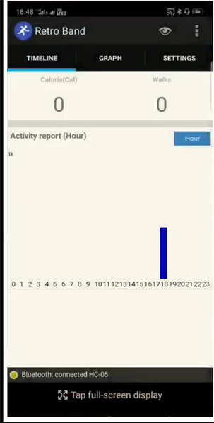
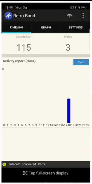
Timeline : It gathers cumulative burned calorie data every hour. You can check how many calories you have burned hourly / daily / monthly.
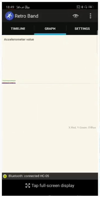
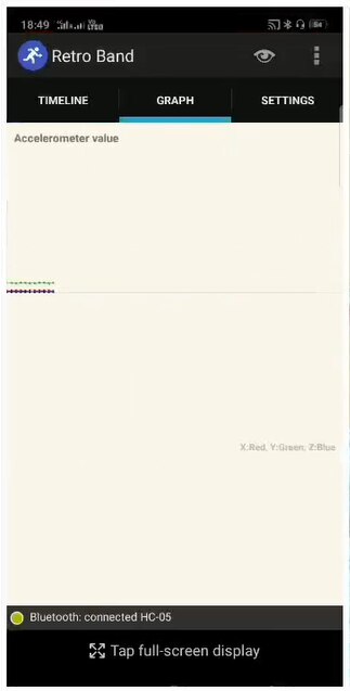
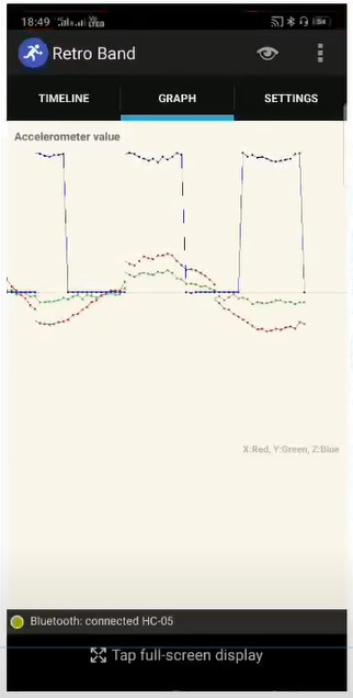
Graph : It shows the graph that is drawn by the data sent from the accelerometer. You can see how 3-axis values alter.
Settings : You can configure the app setting here, and input your weight here.
If you successfully test the app, connect battery and finish the work.

The specification of RetroBand:
- Processor : ATmega328-3.3v(8MHz)
- 32KB Flash(2KB is shared for Bootloader), 2KB RAM, 1KB EEPROM
- Connected with Android exclusive app(supported over v.4.0).
- Calculating calories based on step count.
- Accumulating calorie data and displaying statistics in a monthly/daily/hourly data
- Real-time check of the change of the 3-axis values measured by accelerometer
- Open source
Step 5:Result
Timeline: If Arduino powers on and the pairing process with Retro Band app is done, the board check the accelerometer data 20 times in every 1 second. And it transfer the data to the mobile device once a second. The accelerometer measures x axis / y axis / z axis values, so the band sends 60 values(20 times x 3 axis) of data to the device. The Android app receives the data during two seconds and finds out an interval that user’s movement increase dramatically. The number of user’s movement increase is user’s a step count. The app calculate burned calories based on user’s weight and steps, and accumulates data monthly, daily and hourly as shown in picture below:


Graphical Result : It shows the graph that is drawn by the data sent from the accelerometer. You can see how 3-axis values alter as given in picture below:

Overview:
"Calorie meter and Activity Tracker" consists of an Arduino part and an Android app.
The Arduino has 4 main parts – Arduino Nano, accelerometer(MPU-6050), Bluetooth module(HC-05),battery
The Android app contains of 4 parts – Android UI, Bluetooth manager, Algorithm section, background service.
If Arduino powers on and the pairing process with RetroBand app is done, the board check the accelerometer data 20 times in every 1 second. And it transfer the data to the mobile device once a second. The accelerometer measures x axis / y axis / z axis values, so the band sends 60 values(20 times x 3 axis) of data to the device. The Android app receives the data during two seconds and finds out an interval that user’s movement increase dramatically. The number of user’s movement increase is user’s a step count. The app calculate burned calories based on user’s weight and steps, and accumulates data monthly, daily and hourly.
Conclusion:
My "Calorie Meter and Activity Tracker" is too simple to compare other activity tracking products, but a Bluetooth module and an accelerometer are the basic modules that can be used in any other projects. You can make variables by using the source that I used.
I hope this would be helpful to you.