


 | Enter Your Electronics & Design Project for a chance to win a $200 shopping cart! Back to homepage | Project14 Home |
| Monthly Themes | ||
| Monthly Theme Poll |

Heart rate, body temperature and blood pressure monitoring are very important parameters of human body. Doctors use various kind of medical apparatus like thermometer for checking fever or body temperature, BP monitor for blood pressure measurement and heart rate monitor for heart rate measurement. In this project, I have built an heart rate monitoring wrist band which counts the number of heartbeats in a minute. Here we have used a heartbeat sensor module which senses the heartbeat upon putting a finger on the sensor.
This band convert the analog data(the heart beat) into the digital data by the max30102 module and the result is shown on the OLED display.
COMPONENTS REQUIRED
- Wemos D1 Mini Esp8266
- MAX30102(pulse oximeter sensor)
- 128X64 OLED display
- Male header bergs
- Zero PCB
- Connecting wires
- Velcro straps
- Glue gun with glue sticks
ABOUT COMPONENTS
1. MAX30102

This is a MAX30102 based pulse oximetry and heart-rate monitor breakout board. It includes internal LEDs, photodetectors, optical elements, and low-noise electronics
with ambient light rejection. The MAX30102 provides a complete system solution to ease the design-in process for mobile and wearable devices.
The MAX30102 operates on a single 1.8V power supply and a separate 3.3V power supply for the internal LEDs. Communication is through a standard I2C-compatible interface. The module can be shut down through software with zero standby current, allowing the power rails to remain powered at all times.
It is widely used in wearable devices, fitness assistant devices, smartphones and tables.
2. WEMOS D1 MINI

WeMos- D1 R2 WiFi ESP8266 Development Board is programmable via Arduino IDE. This is an ESP8266 based WiFi enabled microprocessor unit on a Arduino-UNO footprint. That means the board looks and works (in most cases) like an UNO. Several shields, sensors and output devices that are manufactured for the Arduino platform will work on the WeMos-D1R2 with the added advantage of builtin WiFi.
Features of Wemos D1 R2 Wifi -Esp8266 Development Board:
- The D1 R2 is a mini wifi board based on ESP-8266EX
- 11 digital input/output pins, all pins have interrupt/pwm/I2C/one-wire supported(except D0)
- 1 analog input(3.3V max input)
- A Micro USB connection
- A power jack, 9-24V power input
MAX30102 and OLED display connection with Wemos D1 mini


connections :
(MAX30102 WITH WEMOS D1 MINI )
1. SCL --> D1
2. SDA --> D2
3. VIN --> 3V3
4. GND --> GND
(OLED DISPLAY WITH WEMOS D1 MINI )
1. SCL --> D1
2. SDA --> D2
3. VIN --> 5V
4. GND --> GND
PROCEDURE:
STEP1.
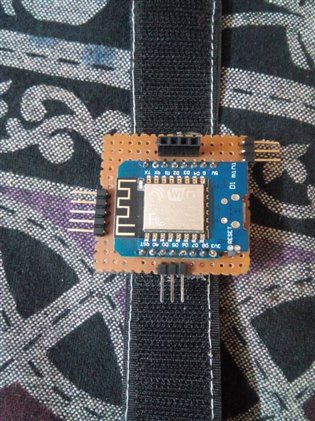
Connect the male and female headers for MAX30102 & OLED display repectively with Wemos D1 mini ESP8266 on a zero PCB, solder the Wemos D1 mini on a zero PCB use male headers for connecting MAX30102 & OLED display and stick the Velcro strap on back of the zero PCB with help of hot glue as shown
STEP2.
connect wires to the MAX30102 and connect a female berg on the other side of the connecting wire, as shown

STEP3.
Connect female header of MAX30102 to the female headers of the band (made in step1)as shown
STEP4.
connect the OLED display to the male header of the wrist band as shown

STEP5.
UPLOAD THIS CODE TO YOUR D1 MINI ESP8266
#include <Adafruit_GFX.h>        //OLED libraries
#include <Adafruit_SSD1306.h>
#include <Wire.h>
#include "MAX30105.h"           //MAX3010x library
#include "heartRate.h"          //Heart rate calculating algorithm


MAX30105 particleSensor;


const byte RATE_SIZE = 4; //Increase this for more averaging. 4 is good.
byte rates[RATE_SIZE]; //Array of heart rates
byte rateSpot = 0;
long lastBeat = 0; //Time at which the last beat occurred
float beatsPerMinute;
int beatAvg;


#define SCREEN_WIDTH 128 // OLED display width, in pixels
#define SCREEN_HEIGHT 64 // OLED display height, in pixels
#define OLED_RESET    -1 // Reset pin # (or -1 if sharing Arduino reset pin)


Adafruit_SSD1306 display(SCREEN_WIDTH, SCREEN_HEIGHT, &Wire, OLED_RESET); //Declaring the display name (display)


static const unsigned char PROGMEM logo2_bmp[] =
{ 0x03, 0xC0, 0xF0, 0x06, 0x71, 0x8C, 0x0C, 0x1B, 0x06, 0x18, 0x0E, 0x02, 0x10, 0x0C, 0x03, 0x10,              //Logo2 and Logo3 are two bmp pictures that display on the OLED if called
0x04, 0x01, 0x10, 0x04, 0x01, 0x10, 0x40, 0x01, 0x10, 0x40, 0x01, 0x10, 0xC0, 0x03, 0x08, 0x88,
0x02, 0x08, 0xB8, 0x04, 0xFF, 0x37, 0x08, 0x01, 0x30, 0x18, 0x01, 0x90, 0x30, 0x00, 0xC0, 0x60,
0x00, 0x60, 0xC0, 0x00, 0x31, 0x80, 0x00, 0x1B, 0x00, 0x00, 0x0E, 0x00, 0x00, 0x04, 0x00,  };


static const unsigned char PROGMEM logo3_bmp[] =
{ 0x01, 0xF0, 0x0F, 0x80, 0x06, 0x1C, 0x38, 0x60, 0x18, 0x06, 0x60, 0x18, 0x10, 0x01, 0x80, 0x08,
0x20, 0x01, 0x80, 0x04, 0x40, 0x00, 0x00, 0x02, 0x40, 0x00, 0x00, 0x02, 0xC0, 0x00, 0x08, 0x03,
0x80, 0x00, 0x08, 0x01, 0x80, 0x00, 0x18, 0x01, 0x80, 0x00, 0x1C, 0x01, 0x80, 0x00, 0x14, 0x00,
0x80, 0x00, 0x14, 0x00, 0x80, 0x00, 0x14, 0x00, 0x40, 0x10, 0x12, 0x00, 0x40, 0x10, 0x12, 0x00,
0x7E, 0x1F, 0x23, 0xFE, 0x03, 0x31, 0xA0, 0x04, 0x01, 0xA0, 0xA0, 0x0C, 0x00, 0xA0, 0xA0, 0x08,
0x00, 0x60, 0xE0, 0x10, 0x00, 0x20, 0x60, 0x20, 0x06, 0x00, 0x40, 0x60, 0x03, 0x00, 0x40, 0xC0,
0x01, 0x80, 0x01, 0x80, 0x00, 0xC0, 0x03, 0x00, 0x00, 0x60, 0x06, 0x00, 0x00, 0x30, 0x0C, 0x00,
0x00, 0x08, 0x10, 0x00, 0x00, 0x06, 0x60, 0x00, 0x00, 0x03, 0xC0, 0x00, 0x00, 0x01, 0x80, 0x00  };


void setup() {
  display.begin(SSD1306_SWITCHCAPVCC, 0x3C); //Start the OLED display
  display.display();
  delay(3000);
  // Initialize sensor
  particleSensor.begin(Wire, I2C_SPEED_FAST); //Use default I2C port, 400kHz speed
  particleSensor.setup(); //Configure sensor with default settings
  particleSensor.setPulseAmplitudeRed(0x0A); //Turn Red LED to low to indicate sensor is running


}


void loop() {
 long irValue = particleSensor.getIR();    //Reading the IR value it will permit us to know if there's a finger on the sensor or not
                                           //Also detecting a heartbeat
if(irValue > 7000){                                           //If a finger is detected
    display.clearDisplay();                                   //Clear the display
    display.drawBitmap(5, 5, logo2_bmp, 24, 21, WHITE);       //Draw the first bmp picture (little heart)
    display.setTextSize(2);                                   //Near it display the average BPM you can display the BPM if you want
    display.setTextColor(WHITE);
    display.setCursor(50,0);
    display.println("BPM");
    display.setCursor(50,18);
    display.println(beatAvg);
    display.display();

  if (checkForBeat(irValue) == true)                        //If a heart beat is detected
  {
    display.clearDisplay();                                //Clear the display
    display.drawBitmap(0, 0, logo3_bmp, 32, 32, WHITE);    //Draw the second picture (bigger heart)
    display.setTextSize(2);                                //And still displays the average BPM
    display.setTextColor(WHITE);
    display.setCursor(50,0);
    display.println("BPM");
    display.setCursor(50,18);
    display.println(beatAvg);
    display.display();
    tone(3,1000);                                        //And tone the buzzer for a 100ms you can reduce it it will be better
    delay(100);
    noTone(3);                                          //Deactivate the buzzer to have the effect of a "bip"
    //We sensed a beat!
    long delta = millis() - lastBeat;                   //Measure duration between two beats
    lastBeat = millis();


    beatsPerMinute = 60 / (delta / 1000.0);           //Calculating the BPM


    if (beatsPerMinute < 255 && beatsPerMinute > 20)               //To calculate the average we strore some values (4) then do some math to calculate the average
    {
      rates[rateSpot++] = (byte)beatsPerMinute; //Store this reading in the array
      rateSpot %= RATE_SIZE; //Wrap variable


      //Take average of readings
      beatAvg = 0;
      for (byte x = 0 ; x < RATE_SIZE ; x++)
        beatAvg += rates[x];
      beatAvg /= RATE_SIZE;
    }
  }


}
  if (irValue < 7000){       //If no finger is detected it inform the user and put the average BPM to 0 or it will be stored for the next measure
     beatAvg=0;
     display.clearDisplay();
     display.setTextSize(1);
     display.setTextColor(WHITE);
     display.setCursor(30,5);
     display.println("Please Place ");
     display.setCursor(30,15);
     display.println("your finger ");
     display.display();
     noTone(3);
     }


}
Now our project is ready, .
connect the usb cable to the Wemos D1 mini micro usb port and power it with help of a adapter,
it will take some time to became stable and then it will show the exact reading
Top Comments