


This is the story of the sage of my vintage battery tester update into the digital world.
We take a good old fashioned, mostly unreliable and hard-to-use tester, and turn it into an equally difficult to use and equally unreliable micro controller powered tester!
So, in a nutshell, the finished project takes:
1) an analog value (battery voltage)
2) converts it into digital (Arduino analogRead)
3) thinks about it a bit and categorizes it into one of 5 output categories, and then
4) using PWM (Arduino analogWrite) outputs an analog value to the gauge, but...
5) Rather than using the full infinite range of the gauge in good ole analog fashion, it steps to 1 of 5 areas... kind of a digital thing to do.
So, short story made much too long... here are the details. And a cat picture for bonus points.
I recently found an old household battery tester while cleaning up, and it was terribly unreliable to use - the gauge doesn't always work, the contacts are sketchy at best. I was about to recycle it, but then I thought the gauge on it might be fun for a project so I tucked it away in a drawer.
When this Data Conversion challenge popped up, I immediately had an idea - maybe I could digitize the thing to make it more useful for my purpose: identify what a battery can be used for.
I've found that some tech items need nearly full batteries to operate well, and even wall clocks can be fussy. The one thing that's not fussy is the cheap little LED string lights - they can light up with nearly dead batteries, though not as bright.
I try not to leave batteries in my devices, because they tend to leak if left over time. So we end up with a pile of batteries that are often still near-new, mixed with nearly-dead well used old batteries.
So I often use my digital multimeter to check if:
a) the battery is still new: generally 1.55v or higher
b) the battery is slightly used but still quite good: 1.4v - 1.55v
c) the battery is kinda low, but will light LED strings brightly: 1.3v - 1.4v
d) the battery is still fine enough for LED string lights: 1.0v - 1.3v -> these I keep as a last resort for the LED lights
e) the battery is too empty for anything useful, and is ready for recycling: less than 1 volt. It's also at a higher risk of leaking at this point.

My stunt batteries randomly happened to all be of different brands, which does help keep them sorted out.
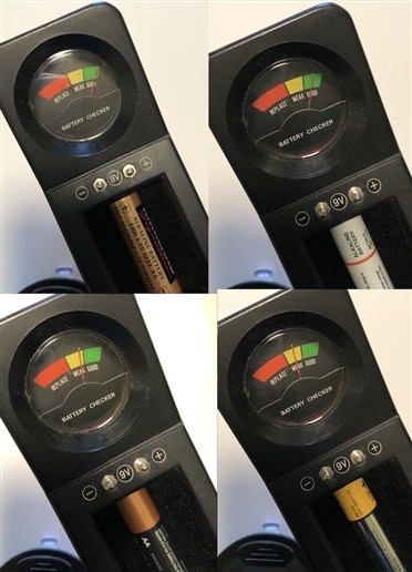
I tried the old battery tester, holding it carefully and having cleaned the contacts. The results are ok, but it really makes even the mostly-dead battery look like it's fine.
So this is where I think, with a little bit of technology, that I can do better!
spoiler alert: I can't 
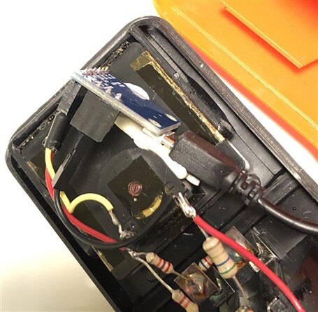
So I took the tester apart to look inside - thankfully, old technology was built in a way that allows easy access = 2 little screws!


And it looks like it has a few resistors making a voltage divider in there - note the extra resistors to also allow testing of a 9 volt battery.
So I clipped on some probes to see the range of values I could expect to see at the gauge itself. Turns out to be very low fraction of a volt values. the 0.18v above is for a new battery.
So to keep things easy I decided to add some wires to intercept the voltage to the gauge, and use it directly as input into a Digispark clone ATTiny85 micro controller, given the low voltages.
Using the full battery voltage might've given a more accurate reading within the controller, but I'm not going back in there now!
I carefully snipped the power side apart to get the new wires in between, but the ground was just an easy direct addition.

I was able to fit the little board directly behind the gauge, using a bit of tack to hold it in place. The USB power cord runs out a hole in the back.
Then I went to program the board, and... it wouldn't program it! argh!
After disconnecting everything, rebooting my computer, and trying a different board, I finally realized I was using a charge-only USB cable. sigh.
But problem solved, and onward we go.
The next issue was that I needed to fine tune the expected Analog-input input ranges to get the desired categories, as well as the desired Analog-out value to properly position the needle of the gauge.
I had some numbers written down, but was faced with some interference which slowed me down considerably:

Also of note, the Analog input for Digisparks is really screwy - the pin numbers are all over the place! make sure to read the docs on that:
https://digistump.com/wiki/digispark/tutorials/basics
Also, from another project I learned that the clones have P5 set to be a reset pin by default. That gets REALLY interesting when you try to use it as a button input 
For this project though, I only needed the one input and the one output, so I only used P0 and P2.
I tried just entering some values and adjusting them to be roughly correct and then tune it, but I was so far off that nothing really worked... so much for my attempt at math-ing it out.
Turns out the Digisparks are really limited and don't have the ability to debug with the usual serial console, so it's a bit tougher to work with in this kind of scenario.
So I grabbed a trusty ole Uno and used it, along with a variable-voltage power supply I received from element14 in a previous competition a few years ago (what a great tool to have!!), to test what all the voltage input ranges end up being in the world of the controller.

After getting some good values figured out, I then did the same to test the desired Analog Output values.
Here's a video of that in action, powered by a Uno:
And here is the finished project:

Here is a video of the final product giving me a hard time and untrustworthy results
You might notice I'm not getting the accuracy I had hoped for. While I was testing with the variable power supply the results were far more consistent, so I don't know why it would be different using the batteries themselves - it's possible the contacts are just not making a good enough connection, but I don't know for sure.
In summary... this was fun to do, and the results are more of a "useless-box" type gadget!
The battery tester now needs external USB power to run the micro controller.
It seems that the micro controller is not really all that accurate and reliable at reading the input voltages properly all the time, but it does actually get a fairly decent result.
So... it's a lot like the old tester was!! sort of sketchy and unreliable... terrible contacts... a gauge with a loose display card that jams the needle... hard to tell if the result can be trusted. Yup! just like vintage tech
Best,
-Nico
Edit: I think the unreliable final results may be a factor of the varying input voltages (computer USB while testing vs USB charger to run it later) - the default uses the I/O voltage, or 5v in this case. I noticed there is an internal 1.1v reference on the ATTiny85 chip that would actually be perfect for the input range we get from the battery tester voltage divider:
analogReference(INTERNAL1V1);
The Arduino code is very simple. I've pasted it here:
/*
  Unnecessarily Complex Battery Tester


  Powered by an ATTiny85 (a Digispark clone), intercepts modified battery voltage, and outputs a more specific reading.


  Instead of the original fully analog battery tester,
    where the battery voltage is modified with a voltage divider to suit the analog gauge,
  the modified voltage is now read by the chip, and the chip outputs a specific level depending on the input value.


  The outputs, however, will point to specific levels:
  > 1.55 volts = New, and the needle points at the far right of the green section on the analog scale
  1.40 - 1.55 volts = Good, and the needle points to the middle of the green section
  1.30 - 1.40 volts = Meh, and points to the middle of the yellow section
  1.0 - 1.30 volts = Lame, and points to the middle of the red section
  < 1.0 is considered to be "no battery", or battery is terrible, and will keep the pointer to the far left.


  As such, we have:
  Analog input -> converted to digital number in chip -> converted to analog (PWM) output value for the gauge.
  However, the analog output value is set to specific levels... kind of digital.


  Using 2 pins:
  * P2 for the input voltage from the battery (after the existing voltage divider)
  * P0 for the output to the gauge
*/


/*
   NOTE: Digispark Analog-Read is wonky when it comes to pin numbering!!
   See https://digistump.com/wiki/digispark/tutorials/basics

    sensorValue = analogRead(1); //Read P2 -> for input, pin number DOES NOT MATCH the port number


    P0, P1, and P4 are capable of hardware PWM (analogWrite).
    pinMode(0, OUTPUT); //0 is P0 -> for output, pin number matches port number

 */
int sensorValue = 0;
int outputValue = 0;


void setup() {
  pinMode(0, OUTPUT); // to gauge
}


void loop() {
  // read the voltage-divider modified value from the battery:
  sensorValue = analogRead(1); //Read P2


  // output to the gauge:


  if (sensorValue > 272) { // > 1.55v = top green
    outputValue = 12;
  }
  else if (sensorValue > 246) {  // > 1.4 v = mid green
    outputValue = 10;
  }
  else if (sensorValue > 227) { // > 1.3 v = mid yellow
    outputValue = 6;
  }
  else if (sensorValue > 168) { // > 1.0 v = mid red
    outputValue = 3;
  }
  else {
    outputValue = 0;
  }


  analogWrite(0,outputValue);

  delay(500); // milliseconds
}
Top Comments