element14 Community
element14 Community
    Register Log In
  • Site
  • Search
  • Log In Register
  • Members
    Members
    • Benefits of Membership
    • Achievement Levels
    • Members Area
    • Personal Blogs
    • Feedback and Support
    • What's New on element14
  • Learn
    Learn
    • Learning Center
    • eBooks
    • STEM Academy
    • Webinars, Training and Events
    • More
  • Technologies
    Technologies
    • 3D Printing
    • FPGA
    • Industrial Automation
    • Internet of Things
    • Power & Energy
    • Sensors
    • More
  • Challenges & Projects
    Challenges & Projects
    • Design Challenges
    • element14 presents
    • Project14
    • Arduino Projects
    • Raspberry Pi Projects
    • More
  • Products
    Products
    • Arduino
    • Dev Tools
    • Manufacturers
    • Raspberry Pi
    • RoadTests & Reviews
    • Avnet Boards Community
    • More
  • Store
    Store
    • Visit Your Store
    • Choose Another Store
      • Europe
      •  Austria (German)
      •  Belgium (Dutch, French)
      •  Bulgaria (Bulgarian)
      •  Czech Republic (Czech)
      •  Denmark (Danish)
      •  Estonia (Estonian)
      •  Finland (Finnish)
      •  France (French)
      •  Germany (German)
      •  Hungary (Hungarian)
      •  Ireland
      •  Israel
      •  Italy (Italian)
      •  Latvia (Latvian)
      •  
      •  Lithuania (Lithuanian)
      •  Netherlands (Dutch)
      •  Norway (Norwegian)
      •  Poland (Polish)
      •  Portugal (Portuguese)
      •  Romania (Romanian)
      •  Russia (Russian)
      •  Slovakia (Slovak)
      •  Slovenia (Slovenian)
      •  Spain (Spanish)
      •  Sweden (Swedish)
      •  Switzerland(German, French)
      •  Turkey (Turkish)
      •  United Kingdom
      • Asia Pacific
      •  Australia
      •  China
      •  Hong Kong
      •  India
      •  Korea (Korean)
      •  Malaysia
      •  New Zealand
      •  Philippines
      •  Singapore
      •  Taiwan
      •  Thailand (Thai)
      • Americas
      •  Brazil (Portuguese)
      •  Canada
      •  Mexico (Spanish)
      •  United States
      Can't find the country/region you're looking for? Visit our export site or find a local distributor.
  • Translate
  • Profile
Electronic Art
  • Challenges & Projects
  • Project14
  • Electronic Art
  • More
  • Cancel
Electronic Art
Blog A Do Nothing Machine - Electronic Sculpture - The Thinker Revisited
  • Blog
  • Forum
  • Documents
  • Events
  • Members
  • Mentions
  • Sub-Groups
  • Tags
  • More
  • Cancel
  • New
Electronic Art requires membership for participation - click to join
Blog Post Actions
  • Subscribe by email
  • More
  • Cancel
  • Share
  • Subscribe by email
  • More
  • Cancel
Group Actions
  • Group RSS
  • More
  • Cancel
Engagement
  • Author Author: jw0752
  • Date Created: 26 Jun 2020 5:27 AM Date Created
  • Views 676 views
  • Likes 17 likes
  • Comments 17 comments
  • electronicartch
  • do_nothing_machine
Related
Recommended

A Do Nothing Machine - Electronic Sculpture - The Thinker Revisited

jw0752
jw0752
26 Jun 2020

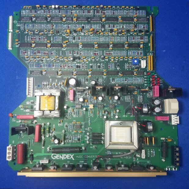
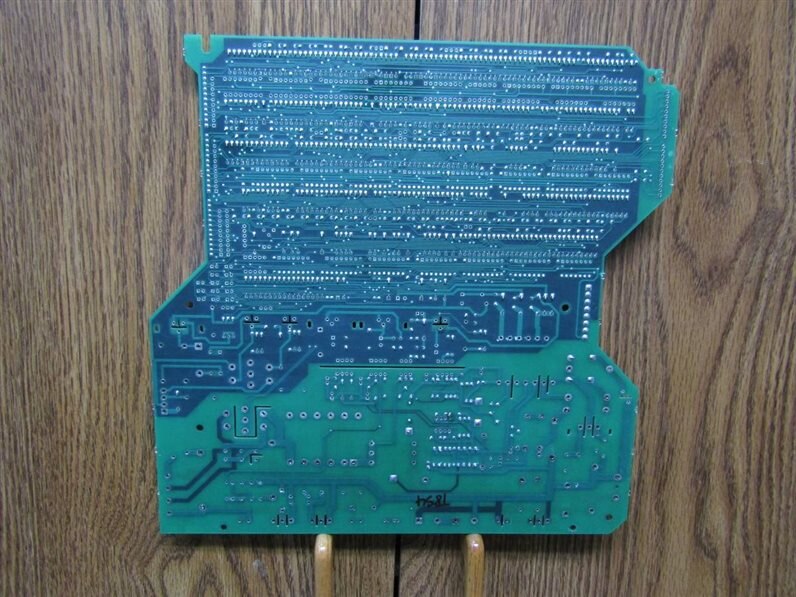
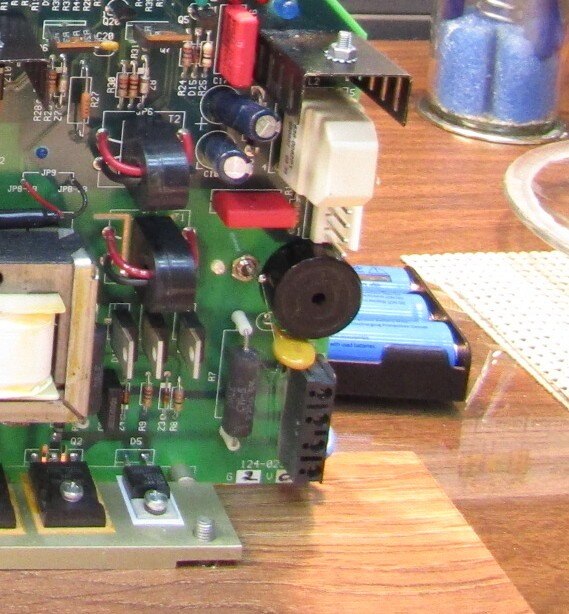
When I built this Electronic Sculpture a couple weeks ago I did not have this contest in mind. I was confronted with a situation where I had a beautiful Electronic Circuit board salvaged from a Dental Panoramic X-Ray Machine. I originally had 3 of these boards and I had salvaged the components from two of them. As I held the third in my hands I began to think that it really had a beauty of its own and since I did not need any more of the parts on it perhaps I could find a better use for it.


This project very quickly took on a life of its own. As you can see the board is quite highly populated. The plan was to begin by adding LEDs to the board. I hoped that a bunch of randomly blinking LEDs would remind the viewers of the robot and android brains that are in the movies. Since it was to simulate a brain I decided to call it The Thinker Revisited. I wanted to use the original components of the board as much as possible. In the end I would only be able to incorporate a dozen or so of the original components as the board is multilayered and the complexity of isolating and using individual components or sections of the circuit proved to be too difficult. After some thought I decided to begin by placing LEDs between the rows of 14 an 16 pin DIP ICs. Holes were drilled and the LEDs were friction fit into the board. Once the spaces between the ICs were used up I continued to place LEDs in other strategic positions.


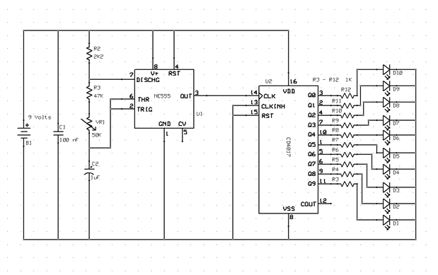
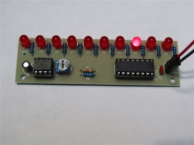
Over the years I have used small Chinese circuit board kits to get my Grandchildren interested in electronics. One of the kits that is always popular is called a scanner.


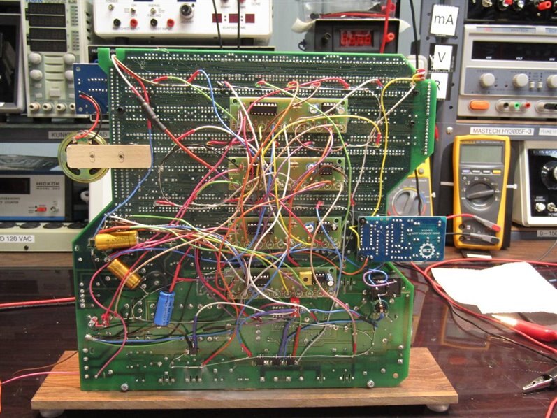
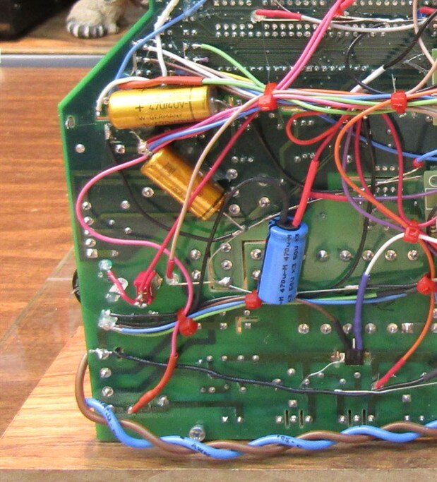
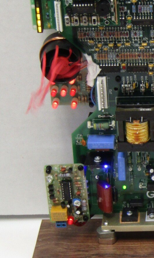
This kit lights the LEDs one by one and then goes back to the beginning and starts over again. In addition it has a variable Pot whereby the speed can be adjusted and with a few substitute components the speed can really be adjusted up or down. I decided to use 3 of these circuits set at different speeds to power the LEDs on the Circuit board sculpture. The LEDs would be wired to each board at random and the difference in speed between the boards would give a random non-repeating sequence to the lights. A fourth Scanner was also build and designed to have a variable speed of from 1 cycle per minute to over 1 cycle per ten minutes. This 4th circuit would power some of the LEDs but it would also enable or trigger other kits that I had now decided to try to incorporate. Here is what the back of the board looked like after the 4 Scanner Kits were installed. The second picture focuses in on the area where the two five volt rails are generated by LM7805s mounted on two of the circuit boards original heat sinks.


I would normally route the wires in a more professional way but this isn't electronics it is Art and I wanted it to look messy and complicated. The four scanner boards are hot glued to the back of the original circuit. The scanner at the bottom is the slow one. It sends a high to the rest of the LEDs not covered by the other scanners and it also sends a High to several MOSFETs which in turn power other kits or it may also trigger the start of a kit directly or though a relay.


At this point I was on a roll. The primary power rail of The Thinker was to be 9 volts to 12 volts and the demands of what I wanted to do also would require two 5 volt rails. One of the 5 volt rails would be used to power the 5 volt kits while the other 5 volt rail would be constantly powered and would supply a PIR motion detector. I wanted The Thinker to sit in a sleep mode and then come to life when someone approached it. I used a Parallax 555-28027 to do this chore.


https://www.newark.com/parallax/555-28027/pir-infared-measurement-sensor/dp/11X5850?ost=Parallax+555


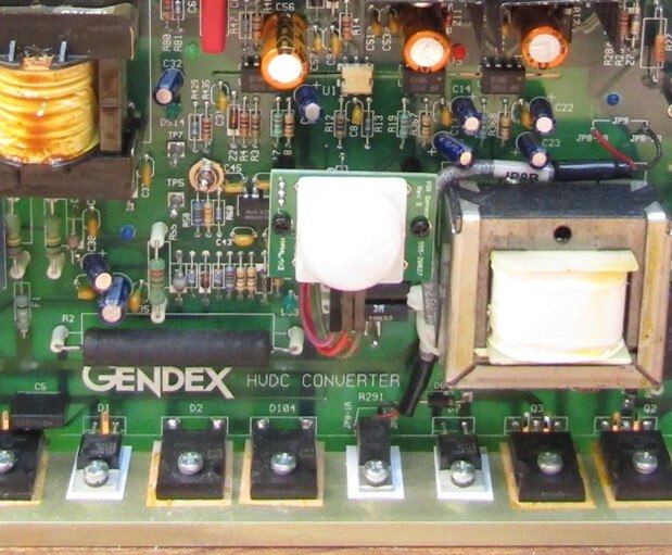
The PIR when activated pulls the gate of a NTD 4906 MOSFET high and this in turn pulls the main ground rail of the rest of the electronics down to true ground.  The PIR was quite quick to reset and initially The Thinker would fall back to sleep unless the audience was constantly moving. A reasonable sized capacitor on the output of the PIR solved this problem. Now there is about 8 seconds before the machine will return to sleep. If you look closely to the top left of the PIR there is a SPDT Center Off switch that is associated with the PIR. This switch allows me to select the use of the PIR, Override the PIR and turn the machine on continuously or in the center off position the machine remains in sleep mode. The only thing that works in the center position is the PIR will glow red when it detects movement in its IR field.


The next challenge was to see how many interesting and impractical kits and circuits I could incorporate on the board. I began to survey the board for spots where I could put another small circuit board without obscuring the beauty of the original board. Since the Gendex HVDC board had an irregular shape this was used to allow me to attach boards around the edges.


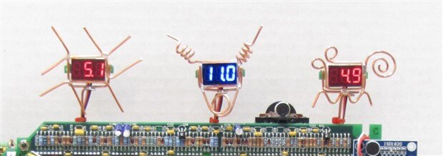
Along the top of the unit there are three volt meters that read out the voltage of the main power supply and then on either side we have the display of the 5 volt supplies. When they were first powered up both of the voltmeters for the 5 volt supplies gave a read out of 5 volts.  Go figure? This was great for the electronics guy in me but the Artist would have nothing to do with it and so both of the meters were intentionally mis-calibrated so that one would read 4.9 Volts and the other 5.1 volts. The artist and the technician had to in the end compromise with my OCD tendencies and at least they were set symmetrically about the original 5 volt point.


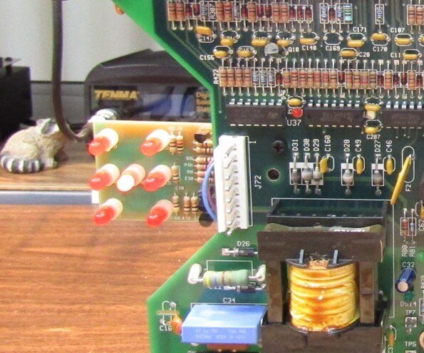
One of the first additions was a small kit that rolls a die. When it is triggered all 7 LEDs, configured so as to look like the face of a Die, are pulsed so quickly that they all appear to be lit. As the pulsing gradually slows you can see that they are indeed flashing and finally they come to rest and stay lit on one of the six die possibilities. This kit is triggered by the slow cycle of the 4th scanner. You can see in the picture that we have rolled snake eye this time.


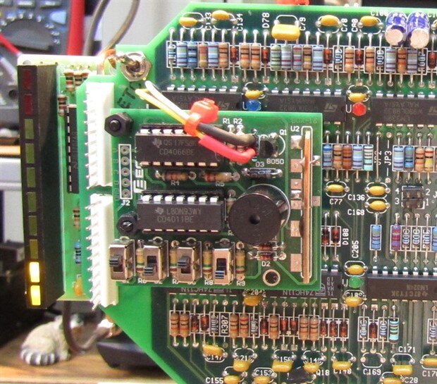
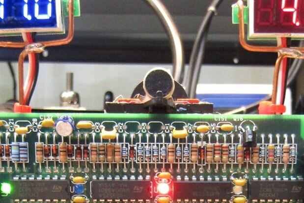
Another kit that is mounted above the Die kit is a siren kit. This circuit has 4 SPST slide switches that allow the user to program 16 different siren sounds. This kit is also triggered by the slow scan of the 4th scanner. I put an on - off switch on this circuit as there are times when a siren is good and times when it is not. The boss goes to sleep early and I am running this crazy thing at 1:00 AM so it needs an OFF switch which is visible above the top left corner of the board. Also visible in this picture is the VU meter on the left side. I happened to have the guts from a kids megaphone and it seemed like a perfect application. The Microphone and amplifier are mounted near the center top of the main board and any sound that is detected is fed to the VU meter. the black disk behind the MIC is a volume control so that the output to the VU can be optimized. The kids like to clap or holler to make the VU meter jump.


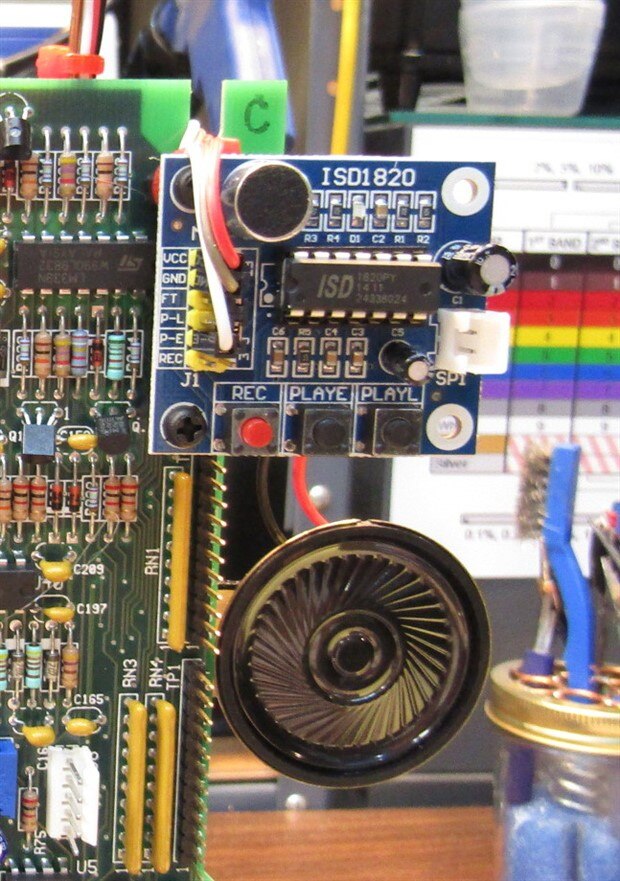
On the right side of the Thinker I have installed a board that wasn't a kit. It is a circuit that allows you to record up to ten seconds of audio and then play it back as many times as you want. Since I have called my sculpture project The Thinker Revisited I have recorded the message " Please don't bother me I'm thinking" on the recorder circuit. This board is also triggered by the slow cycling fourth scanner circuit.


Just to be irritating I have on beeper sonalert that is tied to one of the faster scanners. This unit beeps every time that one specific LED is lit. When you watch the video at the end see if you can determine which one it is. This beeper feature also has a switch which can be seen to the left of the beeper module. This switch was installed specifically to preserve my own sanity.


One of the last kits that I installed was an Infrared switch very similar to the switches that are used to turn on water faucets. This kit has a relatively short range of 15 to 20 cm. I wanted to have the kit run something that was obvious and interactive but I didn't know what that was going to be right away. I have found that sometimes it is good to let things rest and not be too impatient. Sure enough a couple days later I got the idea to add a small fan with red streamers. Now when a person puts their hand near the machine a little fan comes on and blows air on the person. In this picture you can almost see the red streamers flailing about. It looks like the die is processing a roll too. I have included the schematic for the IR Switch. When ever I build these kits I like to improve the schematics that are supplied or go back and reverse engineer a schematic if one is not supplied. This always helps me to better understand the circuit and the possibilities to modify it.


Now that we have had a tour of the individual parts of The Thinker Revisited here is a video that shows you how it all comes together. In the video I have set up the machine and then waited until it went to sleep. As soon as I start the video I moved and the machine begins its cycle.


You don't have permission to edit metadata of this video.
Edit media
x
Upload Preview


I want to thank my friends on the Forum for seeing something in this project and encouraging me to enter it in the Electronic Art Contest. When I was a boy I built a lot of "Do Nothing Machines" using electronic parts and junk that I had salvaged. This is the first do nothing machine of this magnitude I have built in 55 years. I always felt that I was making do nothing machines since I wasn't smart enough to make one that actually did something. Now I learn that I was actually doing Art. Cool! In any case, it was a nice relief from the stress of the politics, pandemic, and civil unrest that currently surrounds all of us.


Thanks for checking it out.


John

Anonymous

Top Comments

  • jw0752
    jw0752 over 1 year ago in reply to fmilburn +6

    Hi Frank,


    Thank you for your kind encouragement. I really liked what you said in an earlier post


    "This machine really does do something - it makes me smile  "


    May I have your permission to use this…

  • jw0752
    jw0752 over 1 year ago in reply to jw0752 +5

    I have been unable to leave this project alone and since June 30th I have added a second voice module and a second VU meter. The VU meter works in tandem with the first VU meter only it is located on the…

  • fmilburn
    fmilburn over 1 year ago +4

    This is awesome John. Every time I look at it I see a new detail. I really like the filigrees and details around the volt meters. This machine really does do something - it makes me smile

Parents
  • jw0752
    jw0752 over 1 year ago

    Honestly if someone had asked me this morning if I was finished with this thing I would have said yes. Then as I made my morning walk an idea began to form and before the walk was over I had committed myself to a few more hours of electronic sculpturing.


    I have decided to give The Thinker arms and hands. In his right hand he is holding a "Clap Switch Module" and in his left hand he is holding a Flashlight that the clap switch will turn on and off. Both the clap switch module and the light are designed to run on 5 volts. Due to the number of things that I have put on the unit I had a concern about power consumption. Therefore the first thing I did before installing the upgrade was to verify the current draw. The test revealed that with everything that could possibly load the circuit functioning the current draw from the main 11 volt source was 400 mA. This reassured me that I was still within an acceptable current draw.


    I got some 12 gauge wire and began to fashion a couple of hand shapes. Once the basic hands were formed I bent them into the positions to hold the module and the flashlight. The flashlight presented a small challenge as the fasten points on the circuit board for the left hand also tied the hand to ground. The metal of the flashlight is also ground but I want it isolated and only pulled to ground through the MOSFET. Therefore the flashlight ended up with a couple layers of electrical tape between the fingers and the flashlight body.


    I have a long history with the Chinese Clap Switch Kits as I have used them in several previous builds. Here is the schematic for the Clap Switch Module:


    I wanted the LED in this circuit to light at the same time as the flashlight. The LED in the circuit turns on with a low from the flip flop and I needed a high to the gate of my flashlight activating MOSFET so I took the signal from the other side of the flip flop which is the junction of R9 - R10 - and the collector of Q3. I already had a spare NTD4906 MOSFET on the board so it was just a matter of running a wire from this point on the board to the gate of the MOSFET. I did buffer this line with a 100R resistor and I also had to pull the gate low with a 10K resistor to ground.


    Here are a couple close-ups of the new hands, flashlight and clap module.


    Finally here is a demo of the clap flashlight in operation:


    You don't have permission to edit metadata of this video.
    Edit media
    x
    Upload Preview


    With this addition I wanted to continue to enhance the interactive nature of the sculpture. Now the unit can sense the presence of a person, turn on a fan when a hand is near the IR detector, modulate the VU meter when noise is heard and turn on a flashlight with a clap or other sharp noise.


    Perhaps it is finished now. (Fingers Crossed)


    John

    • Cancel
    • Up +4 Down
    • Reply
    • More
    • Cancel
  • jw0752
    jw0752 over 1 year ago in reply to jw0752

    I have been unable to leave this project alone and since June 30th I have added a second voice module and a second VU meter. The VU meter works in tandem with the first VU meter only it is located on the opposite side of the unit. It looks like the board has 2 ears that flash. The second voice module allows me to record a second message and I have wired it up to be triggered with the 4th push button that was previously a do nothing button. Now it says a short message when ever the button is pushed.


    Here is a picture of the present machine:


    Another thing that I have done is produce a small operators manual. By numbering a picture of the unit (before the latest modifications) it was possible to talk about the specific modules and features of the unit.


    Do Nothing Machine

    The Thinker Revisited

    Information


    1.        The VU Meter is connected to the Ear (7) so that the intensity of any noise heard by the Ear is displayed on the VU LEDs. The louder the noise the higher the VU display. A second VU meter has been added to the right side of the machine off to the side of the (8) Voice message. Both VU meters are synched to read the same signal.


    2.        The Sound Effects Module is triggered once every cycle of the Slow Scan Module (20) or it can be triggered manually by the #2 button of the Manual Activation Switches (11). There are 4 slide switches on the module that serve as a binary input to the module and depending on their positions select from 16 different sound effects. Try moving the switches and then push the manual activation switch # 2.


    3.        The Siren (Sound Effects) switch is provided as an ON – OFF choice for the sound effects module so that The Thinker can run more quietly when necessary.


    4.        This Voltmeter displays the voltage on the Master 5 volt rail.


    5.        This Voltmeter displays the input voltage from the main power jack (21).


    6.        This Voltmeter displays the voltage on the Service 5 volt Rail.


    7.        The Ear is a microphone and small audio amplifier that picks up ambient sounds and drives the VU Meter (1). The round disk is a volume control knob and can be used to adjust the output level so that it is properly displayed on the VU Meter.


    8.        The Recorded Message Module Number I allows the user to record a 10 second message by pushing and holding the red button. This module currently is playing back “Please don’t bother me, I’m Thinking”. This module is triggered once each cycle of the Slow Scan Module (20) or it can be triggered by button #3 of the Manual Activation Switches (11). A second Recorded Message Module II has been added below the first module. This second module is only triggered by the #4 button of the Manual Activation Switches (11).


    9.        The Beep Switch is used to turn the beep (10) sound off or on depending on the display noise requirements.


    10.      The Beeper is tied to one of the LEDs that are driven by the LED Scan Modules (19). It can be turned on and off by the Beep Switch (9)>


    11.      The Manual Activation Switches provide interaction with the viewer. From left to right the switches are numbered 1 through 4 and activate, The Dice Module (15), The Siren Sound Effects Module (2), The Voice Module I (8), and the  Voice Module II.


    12.      The PIR is a passive infrared sensor that can be triggered from up to 30 feet away. Any heat source, such as a human, that moves in its field causes it to turn on and trigger the rest of the machine to turn on. Once turned on, the machine will run for about 8 seconds before it shuts down again unless the PIR is retriggered by movement. If you want the machine to keep running you have to keep moving. The PIR is powered by the Master 5 volt rail and is on automatically regardless of any switch setting as long as power is applied to the main power jack (21).


    13.      PIR OFF ON Control Switch is provided to allow the user to operate the unit in two active modes. When the switch is up the unit is in continuous mode and is and not affected by the PIR. When the switch is all the way down the unit is in PIR Mode and will turn on with any movement detected by the PIR (12). In the center Off position the PIR remains functional but it can not turn the unit ON. The unit is effectively in sleep mode. The only way to totally turn off the unit is to unplug the main power from the Power Jack (21)


    14.      The Infrared Sensor is a short range (15 cm) sensor much like those used to turn on the water, dispense the soap or flush the toilets in a restroom. On this machine it turns on the Fan (16) that runs for a few seconds when triggered. Depending on the ambient lighting this sensor may trigger with variable range.


    15.      The Die (One Dice) is rolled once each time the slow scan (20) cycles. When rolled all of the LEDs will light and then blink and eventually come to rest on one of the 6 possibilities for a Die to display. The Die can also be triggered by #1 button of the Manual Activation Switches (11).


    16.      The Fan is driven by the Infrared Sensor (14) and comes on for a few seconds each time something gets into the trigger range of the IR sensor. The red streamers were installed to demonstrate the air movement for presentation videos.


    17.      The Clap Switch Module is sensitive to sharp sounds like clicks and claps. When it is triggered it will turn on the Flashlight (18). The unit will remain in the ON status until a second click or clap is detected.


    18.      The Flashlight is turned ON and OFF by the Clap Switch (17). The flashlight can also be disabled by pushing the button on the end of its handle just as one would turn it on or off in normal use. If the flashlight doesn’t seem to be working try pushing the black pushbutton on its end and clap again.


    19.      The LED Scan modules are Ripple counters that are driven by a 555 Timer. There are three scan modules each of which operates at a different clock speed. This helps to give the LED flashing a random appearance. Each module’s speed can be controlled by the trimmer pot (23) on its board.


    20.      The Slow Scan module is a Ripple Counter that has a modified 555 Timer that runs at a much slower speed. The cycle time of the slow scan module can vary from1 minute to over ten minutes. IT is currently set at about a 3 minute cycle. The speed is controlled by the slow scan speed Adjustment (24).


    21.      The Main Power Jack can accept 8 to13 volts DC with the positive rail on the center connector of the jack. The machine is polarity protected by a diode so if you are trying a different power supply and it doesn’t work it just might have the wrong polarity. The diode will keep you from damaging the unit.


    22.      The Driver MOSFETs are NTD 4906 devices that are used to turn the machine itself (left most MOSFET on the back) on, or one of the other modules. The MOSFETs work by pulling a rail to ground and thus providing a closed circuit for a device. The Slow Scanner drives three of the MOSFETs and the PIR drives the one for main power turn on.


    23.      These are the Scan Speed adjustments described in (19).


    24.      This is the slow Scan Speed adjustment described in (20)

    • Cancel
    • Up +5 Down
    • Reply
    • More
    • Cancel
Comment
  • jw0752
    jw0752 over 1 year ago in reply to jw0752

    I have been unable to leave this project alone and since June 30th I have added a second voice module and a second VU meter. The VU meter works in tandem with the first VU meter only it is located on the opposite side of the unit. It looks like the board has 2 ears that flash. The second voice module allows me to record a second message and I have wired it up to be triggered with the 4th push button that was previously a do nothing button. Now it says a short message when ever the button is pushed.


    Here is a picture of the present machine:


    Another thing that I have done is produce a small operators manual. By numbering a picture of the unit (before the latest modifications) it was possible to talk about the specific modules and features of the unit.


    Do Nothing Machine

    The Thinker Revisited

    Information


    1.        The VU Meter is connected to the Ear (7) so that the intensity of any noise heard by the Ear is displayed on the VU LEDs. The louder the noise the higher the VU display. A second VU meter has been added to the right side of the machine off to the side of the (8) Voice message. Both VU meters are synched to read the same signal.


    2.        The Sound Effects Module is triggered once every cycle of the Slow Scan Module (20) or it can be triggered manually by the #2 button of the Manual Activation Switches (11). There are 4 slide switches on the module that serve as a binary input to the module and depending on their positions select from 16 different sound effects. Try moving the switches and then push the manual activation switch # 2.


    3.        The Siren (Sound Effects) switch is provided as an ON – OFF choice for the sound effects module so that The Thinker can run more quietly when necessary.


    4.        This Voltmeter displays the voltage on the Master 5 volt rail.


    5.        This Voltmeter displays the input voltage from the main power jack (21).


    6.        This Voltmeter displays the voltage on the Service 5 volt Rail.


    7.        The Ear is a microphone and small audio amplifier that picks up ambient sounds and drives the VU Meter (1). The round disk is a volume control knob and can be used to adjust the output level so that it is properly displayed on the VU Meter.


    8.        The Recorded Message Module Number I allows the user to record a 10 second message by pushing and holding the red button. This module currently is playing back “Please don’t bother me, I’m Thinking”. This module is triggered once each cycle of the Slow Scan Module (20) or it can be triggered by button #3 of the Manual Activation Switches (11). A second Recorded Message Module II has been added below the first module. This second module is only triggered by the #4 button of the Manual Activation Switches (11).


    9.        The Beep Switch is used to turn the beep (10) sound off or on depending on the display noise requirements.


    10.      The Beeper is tied to one of the LEDs that are driven by the LED Scan Modules (19). It can be turned on and off by the Beep Switch (9)>


    11.      The Manual Activation Switches provide interaction with the viewer. From left to right the switches are numbered 1 through 4 and activate, The Dice Module (15), The Siren Sound Effects Module (2), The Voice Module I (8), and the  Voice Module II.


    12.      The PIR is a passive infrared sensor that can be triggered from up to 30 feet away. Any heat source, such as a human, that moves in its field causes it to turn on and trigger the rest of the machine to turn on. Once turned on, the machine will run for about 8 seconds before it shuts down again unless the PIR is retriggered by movement. If you want the machine to keep running you have to keep moving. The PIR is powered by the Master 5 volt rail and is on automatically regardless of any switch setting as long as power is applied to the main power jack (21).


    13.      PIR OFF ON Control Switch is provided to allow the user to operate the unit in two active modes. When the switch is up the unit is in continuous mode and is and not affected by the PIR. When the switch is all the way down the unit is in PIR Mode and will turn on with any movement detected by the PIR (12). In the center Off position the PIR remains functional but it can not turn the unit ON. The unit is effectively in sleep mode. The only way to totally turn off the unit is to unplug the main power from the Power Jack (21)


    14.      The Infrared Sensor is a short range (15 cm) sensor much like those used to turn on the water, dispense the soap or flush the toilets in a restroom. On this machine it turns on the Fan (16) that runs for a few seconds when triggered. Depending on the ambient lighting this sensor may trigger with variable range.


    15.      The Die (One Dice) is rolled once each time the slow scan (20) cycles. When rolled all of the LEDs will light and then blink and eventually come to rest on one of the 6 possibilities for a Die to display. The Die can also be triggered by #1 button of the Manual Activation Switches (11).


    16.      The Fan is driven by the Infrared Sensor (14) and comes on for a few seconds each time something gets into the trigger range of the IR sensor. The red streamers were installed to demonstrate the air movement for presentation videos.


    17.      The Clap Switch Module is sensitive to sharp sounds like clicks and claps. When it is triggered it will turn on the Flashlight (18). The unit will remain in the ON status until a second click or clap is detected.


    18.      The Flashlight is turned ON and OFF by the Clap Switch (17). The flashlight can also be disabled by pushing the button on the end of its handle just as one would turn it on or off in normal use. If the flashlight doesn’t seem to be working try pushing the black pushbutton on its end and clap again.


    19.      The LED Scan modules are Ripple counters that are driven by a 555 Timer. There are three scan modules each of which operates at a different clock speed. This helps to give the LED flashing a random appearance. Each module’s speed can be controlled by the trimmer pot (23) on its board.


    20.      The Slow Scan module is a Ripple Counter that has a modified 555 Timer that runs at a much slower speed. The cycle time of the slow scan module can vary from1 minute to over ten minutes. IT is currently set at about a 3 minute cycle. The speed is controlled by the slow scan speed Adjustment (24).


    21.      The Main Power Jack can accept 8 to13 volts DC with the positive rail on the center connector of the jack. The machine is polarity protected by a diode so if you are trying a different power supply and it doesn’t work it just might have the wrong polarity. The diode will keep you from damaging the unit.


    22.      The Driver MOSFETs are NTD 4906 devices that are used to turn the machine itself (left most MOSFET on the back) on, or one of the other modules. The MOSFETs work by pulling a rail to ground and thus providing a closed circuit for a device. The Slow Scanner drives three of the MOSFETs and the PIR drives the one for main power turn on.


    23.      These are the Scan Speed adjustments described in (19).


    24.      This is the slow Scan Speed adjustment described in (20)

    • Cancel
    • Up +5 Down
    • Reply
    • More
    • Cancel
Children
No Data
Element14

element14 is the first online community specifically for engineers. Connect with your peers and get expert answers to your questions.

  • Members
  • Learn
  • Technologies
  • Challenges & Projects
  • Products
  • Store
  • About Us
  • Feedback & Support
  • FAQs
  • Terms of Use
  • Privacy Policy
  • Legal and Copyright Notices
  • Sitemap
  • Cookies

An Avnet Company © 2022 Premier Farnell Limited. All Rights Reserved.

Premier Farnell Ltd, registered in England and Wales (no 00876412), registered office: Farnell House, Forge Lane, Leeds LS12 2NE.

ICP 备案号 10220084.

Follow element14

  • Facebook
  • Twitter
  • linkedin
  • YouTube