element14 Community
element14 Community
    Register Log In
  • Site
  • Search
  • Log In Register
  • About Us
  • Community Hub
    Community Hub
    • What's New on element14
    • Feedback and Support
    • Benefits of Membership
    • Personal Blogs
    • Members Area
    • Achievement Levels
  • Learn
    Learn
    • Ask an Expert
    • eBooks
    • element14 presents
    • Learning Center
    • Tech Spotlight
    • STEM Academy
    • Webinars, Training and Events
    • Learning Groups
  • Technologies
    Technologies
    • 3D Printing
    • FPGA
    • Industrial Automation
    • Internet of Things
    • Power & Energy
    • Sensors
    • Technology Groups
  • Challenges & Projects
    Challenges & Projects
    • Design Challenges
    • element14 presents Projects
    • Project14
    • Arduino Projects
    • Raspberry Pi Projects
    • Project Groups
  • Products
    Products
    • Arduino
    • Avnet Boards Community
    • Dev Tools
    • Manufacturers
    • Multicomp Pro
    • Product Groups
    • Raspberry Pi
    • RoadTests & Reviews
  • Store
    Store
    • Visit Your Store
    • Choose another store...
      • Europe
      •  Austria (German)
      •  Belgium (Dutch, French)
      •  Bulgaria (Bulgarian)
      •  Czech Republic (Czech)
      •  Denmark (Danish)
      •  Estonia (Estonian)
      •  Finland (Finnish)
      •  France (French)
      •  Germany (German)
      •  Hungary (Hungarian)
      •  Ireland
      •  Israel
      •  Italy (Italian)
      •  Latvia (Latvian)
      •  
      •  Lithuania (Lithuanian)
      •  Netherlands (Dutch)
      •  Norway (Norwegian)
      •  Poland (Polish)
      •  Portugal (Portuguese)
      •  Romania (Romanian)
      •  Russia (Russian)
      •  Slovakia (Slovak)
      •  Slovenia (Slovenian)
      •  Spain (Spanish)
      •  Sweden (Swedish)
      •  Switzerland(German, French)
      •  Turkey (Turkish)
      •  United Kingdom
      • Asia Pacific
      •  Australia
      •  China
      •  Hong Kong
      •  India
      •  Korea (Korean)
      •  Malaysia
      •  New Zealand
      •  Philippines
      •  Singapore
      •  Taiwan
      •  Thailand (Thai)
      • Americas
      •  Brazil (Portuguese)
      •  Canada
      •  Mexico (Spanish)
      •  United States
      Can't find the country/region you're looking for? Visit our export site or find a local distributor.
  • Translate
  • Profile
  • Settings
Holiday Special 20
  • Challenges & Projects
  • Project14
  • Holiday Special 20
  • More
  • Cancel
Holiday Special 20
Blog Musical Card With Gyro Control LED's
  • Blog
  • Forum
  • Documents
  • Events
  • Polls
  • Files
  • Members
  • Mentions
  • Sub-Groups
  • Tags
  • More
  • Cancel
  • New
Join Holiday Special 20 to participate - click to join for free!
  • Share
  • More
  • Cancel
Group Actions
  • Group RSS
  • More
  • Cancel
Engagement
  • Author Author: harjinagi
  • Date Created: 13 Jan 2021 7:45 PM Date Created
  • Views 1522 views
  • Likes 10 likes
  • Comments 5 comments
  • mpu-6050
  • element14_blog
  • greeting_card_technology
  • holiday special 20
  • proving science
  • new_year_projects
  • arduino project
  • audio amplifier
  • isd1820
  • e14 community
  • element 14
  • christmas projects
  • elf14presents_wishlist
  • element-14
  • cool arduino projects
  • christmas
  • simple arduino projects
  • holidayspecial20ch
  • arduino project ideas
  • led controller
  • arduino uno project
  • arduino projects for beginners
  • diy project
Related
Recommended

Musical Card With Gyro Control LED's

harjinagi
harjinagi
13 Jan 2021
image

Holiday Special 20

Enter Your Holiday Project for a chance to win a tool kit bundle, shopping cart, and gifts to give to other members!

Submit an EntrySubmit an Entry  Back to homepage image
Project14 Home
Monthly Themes
Monthly Theme Poll


You don't have permission to edit metadata of this video.
Edit media
x
image
Upload Preview
image


Hello Everyone, My name is Harji Nagi. I am currently a third year student studying electronics and communication engineering from Pranveer Singh Institute Of Technology, Kanpur(UP).I have a keen interest in robotics,arduino,Artificial Intelligence and Analog electronics.

Today I made a greeting card specially for Holiday Special 20 which consist of  MPU-6050MPU-6050 for controlling 3 LEDs on the card. The gyroscope is programmed to detect the tilt in the card and then turn on the respective tilted LED and ISD1820 a small Voice Recorder and Playback module that can do the multi-segment recording.application with the adjustment of the on-board resistor.

re:

1) Arduino UNO R3

2) MPU-6050MPU-6050

3) 3*LED's

4) ISD1820 Voice record and play chip

5) 3*100 ohm resistors

6) Thermocol

7) Female and male headers

8) Wires

9) On/Off Switch

10) 3.7V Battery for ISD1820 chip

11) 8V,1.5 Amp Battery for Arduino

12) Chart Papers

13) Double Sider Tape

14) Fevicol

15) Stickers

Connection Diagram for controlling Leds:

image

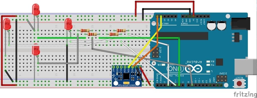
LEDs :-const int frontLed = 3;const int bottomLed = 5;const int rightLed = 6;const int leftLed = 9;

And for the MPU-6050MPU-6050. The MPU-6050MPU-6050 must be connected to ground and 5V+, after that connect SDA to A4 (analog 4), SCL to A5(analog 5).

You are done with the connections now.

Before uploading the code you would require to download 2 libraries.

1. https://www.i2cdevlib.com/usage

2. https://playground.arduino.cc/Main/MPU-6050

Upload the code after doing the required connections.

Code :

#define SIMPLE_IMPLEMENTATION false


const int frontLed = 3;
const int bottomLed = 5;
const int rightLed = 6;
const int leftLed = 9;
long int lastPrintTime;


typedef struct
{
byte pin;
byte positionInsideGroup;
char thePosition; // Left, Right, Up, Down
byte minAngle;
byte maxAngle;
} ledConfig;


ledConfig leds[] = {
{3, 1, ‘u’, 31, 45},
{12, 2, ‘u’, 16, 30},
{11, 3, ‘u’, 5, 15},
{5, 1, ‘d’, 5, 15},
{6, 2, ‘d’, 16, 30},
{7, 3, ‘d’, 31, 45},
{8 , 1, ‘r’, 5, 23},
{9, 2, ‘r’, 24, 45},
{10, 1, ‘l’, 5, 23},
{4, 2, ‘l’, 24, 45},
};


#include “I2Cdev.h”
#include “MPU6050_6Axis_MotionApps20.h”
#if I2CDEV_IMPLEMENTATION == I2CDEV_ARDUINO_WIRE
#include “Wire.h”
#endif


MPU6050 mpu;


bool dmpReady = false; // set true if DMP init was successful
uint8_t mpuIntStatus; // holds actual interrupt status byte from MPU
uint8_t devStatus; // return status after each device operation (0 = success, !0 = error)
uint16_t packetSize; // expected DMP packet size (default is 42 bytes)
uint16_t fifoCount; // count of all bytes currently in FIFO
uint8_t fifoBuffer[64]; // FIFO storage buffer


// orientation/motion vars
Quaternion q; // [w, x, y, z] quaternion container
VectorInt16 aa; // [x, y, z] accel sensor measurements
VectorInt16 aaReal; // [x, y, z] gravity-free accel sensor measurements
VectorInt16 aaWorld; // [x, y, z] world-frame accel sensor measurements
VectorFloat gravity; // [x, y, z] gravity vector
float euler[3]; // [psi, theta, phi] Euler angle container
float ypr[3]; // [yaw, pitch, roll] yaw/pitch/roll container and gravity vector
volatile bool mpuInterrupt = false; // indicates whether MPU interrupt pin has gone high


void setup()
{
#if I2CDEV_IMPLEMENTATION == I2CDEV_ARDUINO_WIRE
Wire.begin();
TWBR = 24; // 400kHz I2C clock (200kHz if CPU is 8MHz)
#elif I2CDEV_IMPLEMENTATION == I2CDEV_BUILTIN_FASTWIRE
Fastwire::setup(400, true);
#endif


Serial.begin(9600);
while (!Serial); // wait for Leonardo enumeration, others continue immediately
Serial.println(F(“Initializing I2C devices…”));
mpu.initialize();
Serial.println(F(“Testing device connections…”));
Serial.println(mpu.testConnection() ? F(“MPU6050 connection successful”) : F(“MPU6050 connection failed”));
Serial.println(F(“Initializing DMP…”));
devStatus = mpu.dmpInitialize();
mpu.setXGyroOffset(220);
mpu.setYGyroOffset(76);
mpu.setZGyroOffset(-85);
mpu.setZAccelOffset(1788); // 1688 factory default for my test chip
if (devStatus == 0) {
// turn on the DMP, now that it’s ready
Serial.println(F(“Enabling DMP…”));
mpu.setDMPEnabled(true);
Serial.println(F(“Enabling interrupt detection (Arduino external interrupt 0)…”));
attachInterrupt(0, dmpDataReady, RISING);
mpuIntStatus = mpu.getIntStatus();
Serial.println(F(“DMP ready! Waiting for first interrupt…”));
dmpReady = true;
packetSize = mpu.dmpGetFIFOPacketSize();
} else {
Serial.print(F(“DMP Initialization failed (code “));
Serial.print(devStatus);
Serial.println(F(“)”));
}
if (SIMPLE_IMPLEMENTATION) {
initializeLEDsSimple();
} else {
initializeLEDsMultiple();
}
lastPrintTime = millis();
}


void loop()
{
if (!dmpReady) return;
mpuInterrupt = false;
mpuIntStatus = mpu.getIntStatus();
fifoCount = mpu.getFIFOCount();
if ((mpuIntStatus & 0x10) || fifoCount == 1024) {
mpu.resetFIFO();
Serial.println(F(“FIFO overflow!”));
} else if (mpuIntStatus & 0x02) {
while (fifoCount < packetSize) {
fifoCount = mpu.getFIFOCount();
}
mpu.getFIFOBytes(fifoBuffer, packetSize);
fifoCount -= packetSize;
mpu.dmpGetQuaternion(&q, fifoBuffer);
mpu.dmpGetGravity(&gravity, &q);
mpu.dmpGetYawPitchRoll(ypr, &q, &gravity);
int x = ypr[0] * 180/M_PI;
int y = ypr[1] * 180/M_PI;
int z = ypr[2] * 180/M_PI;
Serial.print(y);Serial.print(“\t”);Serial.println(z);
if (SIMPLE_IMPLEMENTATION) {
flashLEDsSimple(x, y, z);
} else {
flashLEDsMultiple(x, y, z);
}
}
}


void initializeLEDsSimple()
{
pinMode(frontLed, OUTPUT);
pinMode(bottomLed, OUTPUT);
pinMode(rightLed, OUTPUT);
pinMode(leftLed, OUTPUT);
}


void initializeLEDsMultiple()
{
for (int i=0; i<10; i++) {
Serial.println(leds[i].pin);
pinMode(leds[i].pin, OUTPUT);
}
delay(3000);
}


void flashLEDsSimple(int x, int y, int z)
{
if (y > 0) {
analogWrite(rightLed, y*4);
analogWrite(leftLed, 0);
} else {
analogWrite(leftLed, y*4*-1);
analogWrite(rightLed, 0);
}
if (z > 0) {
analogWrite(bottomLed, z*4);
analogWrite(frontLed, 0);
} else {
analogWrite(frontLed, z*4*-1);
analogWrite(bottomLed, 0);
}
}


void flashLEDsMultiple(int x, int y, int z)
{
for (int i=0; i<10; i++) {
//Serial.print(z);Serial.print(“,”);Serial.print(leds[i].thePosition);Serial.print(“,”);Serial.println(leds[i].minAngle);
bool modified = false;
if (z < 0 && leds[i].thePosition == ‘u’ && abs(z) > leds[i].minAngle) {
digitalWrite(leds[i].pin, HIGH);
modified = true;
}
if (z > 0 && leds[i].thePosition == ‘d’ && abs(z) > leds[i].minAngle) {
digitalWrite(leds[i].pin, HIGH);
modified = true;
}
if (y < 0 && leds[i].thePosition == ‘l’ && abs(y) > leds[i].minAngle) {
digitalWrite(leds[i].pin, HIGH);
modified = true;
}
if (y > 0 && leds[i].thePosition == ‘r’ && abs(y) > leds[i].minAngle) {
digitalWrite(leds[i].pin, HIGH);
modified = true;
}
if (!modified) {
digitalWrite(leds[i].pin, LOW);
}
}
}


void dmpDataReady()
{
mpuInterrupt = true;
}


Connections for ISD1820:

ISD1820 must be connected to ground and its operating voltage is 2.2V to 5V.And connect the speaker at sp+ and sp- .

Press the red button(rec) to start recording the song,voice or any greeting message.It will record not more than 20 seconds.

After recording press Playback to play the recorded message.

image

                                                        Assembling:

                                                                                Step 1:

                                                                                                         image

Take two thermocol Sheets and slice it according to size of the components to be placed on it.

                                                            Step 2:

After slicing thermocol it will look similar to it.

                                                                                                         image

                                                            Step 3:

Now placed the thermocol on each other and stick it either with glue or with double sider tape.

                                                                                                             
image

                                                            Step 4:

Now place all the electronic components and do the connection according to given schematic diagram.And apply cello tape so that the components remain fixed in their position.     
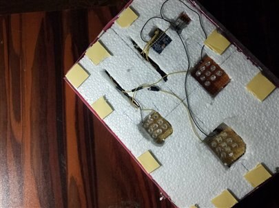
           imageimage

                                                              Step 5:

Now cover  these components with the help of colorful chart papers and decorate it to make it more attractive.

                                                                 imageimage

                                                                      Step 6:

Now the card is ready .On switching on the power button the gyroscope detects the tilt in the card and then turn on the respective tilted LED and on pressing the playback button of ISD182 ,it plays a melodious song .Please watch this vedio for more information.I hope you enjoyed this tutorial.

You don't have permission to edit metadata of this video.
Edit media
x
image
Upload Preview
image


WISH YOU HAPPY NEW YEAR

  • Sign in to reply

Top Comments

  • dubbie
    dubbie over 4 years ago +2
    Harji, A great project with some good ideas as well as being nicely packaged. The idea to use LED arrays to indicate orientation is interesting and I might have to think about how I might be able to use…
  • seharfatima
    seharfatima over 4 years ago +2
    Nice and innovative project with good use of gyro sensor in greeting card .I will apply this concept in my future projects. And all the best for the contest results(•‿•)
  • shabaz
    shabaz over 4 years ago +1
    Hi Harji, Interesting and well-documented project! It was interesting to see your results with the sound recorder board - I'll have to order some of those sometime to experiment with them : ) Incidentally…
  • harjinagi
    harjinagi over 4 years ago in reply to seharfatima

    Thanks Sehar for wishes and compliment.

    • Cancel
    • Vote Up +1 Vote Down
    • Sign in to reply
    • More
    • Cancel
  • seharfatima
    seharfatima over 4 years ago

    Nice and innovative project with good use of gyro sensor in greeting card .I will apply this concept in my future projects.

    And all the best for the contest results(•‿•)

    • Cancel
    • Vote Up +2 Vote Down
    • Sign in to reply
    • More
    • Cancel
  • harjinagi
    harjinagi over 4 years ago in reply to shabaz

    Hi Shabaz,


    The Atmel processor chips have built-in positive and negative clamping diodes on all the I/O pins that do offer some protection from ESD type events.

    But  for safety,I provided isolation tape under and over all components including ISD1820 and Arduino.I don't have much wires, so probably taping them too will do as shielding and doesn't generate a lot of static electricity .image

    And as seen in the picture the base of the Arduino is kept opposite  from polystyrene and cover the base with isolation tape and chart paper so i hope it will not cause any damage to my Arduino   .


    And thanks for positive response.


    • Cancel
    • Vote Up +1 Vote Down
    • Sign in to reply
    • More
    • Cancel
  • shabaz
    shabaz over 4 years ago

    Hi Harji,


    Interesting and well-documented project! It was interesting to see your results with the sound recorder board - I'll have to order some of those sometime to experiment with them : )

    Incidentally, the white board you're using, doesn't it generate a lot of static electricity? It looks like 'expanded polystyrene'. If it does, be careful when you remove the electronics, in case it damages the Arduino.

    • Cancel
    • Vote Up +1 Vote Down
    • Sign in to reply
    • More
    • Cancel
  • dubbie
    dubbie over 4 years ago

    Harji,


    A great project with some good ideas as well as being nicely packaged. The idea to use LED arrays to indicate orientation is interesting and I might have to think about how I might be able to use that concept in future projects.


    Dubbie

    • Cancel
    • Vote Up +2 Vote Down
    • Sign in to reply
    • More
    • Cancel
element14 Community

element14 is the first online community specifically for engineers. Connect with your peers and get expert answers to your questions.

  • Members
  • Learn
  • Technologies
  • Challenges & Projects
  • Products
  • Store
  • About Us
  • Feedback & Support
  • FAQs
  • Terms of Use
  • Privacy Policy
  • Legal and Copyright Notices
  • Sitemap
  • Cookies

An Avnet Company © 2025 Premier Farnell Limited. All Rights Reserved.

Premier Farnell Ltd, registered in England and Wales (no 00876412), registered office: Farnell House, Forge Lane, Leeds LS12 2NE.

ICP 备案号 10220084.

Follow element14

  • X
  • Facebook
  • linkedin
  • YouTube