element14 Community
element14 Community
    Register Log In
  • Site
  • Search
  • Log In Register
  • Members
    Members
    • Benefits of Membership
    • Achievement Levels
    • Members Area
    • Personal Blogs
    • Feedback and Support
    • What's New on element14
  • Learn
    Learn
    • Learning Center
    • eBooks
    • STEM Academy
    • Webinars, Training and Events
    • More
  • Technologies
    Technologies
    • 3D Printing
    • FPGA
    • Industrial Automation
    • Internet of Things
    • Power & Energy
    • Sensors
    • More
  • Challenges & Projects
    Challenges & Projects
    • Design Challenges
    • element14 presents
    • Project14
    • Arduino Projects
    • Raspberry Pi Projects
    • More
  • Products
    Products
    • Arduino
    • Dev Tools
    • Manufacturers
    • Raspberry Pi
    • RoadTests & Reviews
    • Avnet Boards Community
    • More
  • Store
    Store
    • Visit Your Store
    • Choose Another Store
      • Europe
      •  Austria (German)
      •  Belgium (Dutch, French)
      •  Bulgaria (Bulgarian)
      •  Czech Republic (Czech)
      •  Denmark (Danish)
      •  Estonia (Estonian)
      •  Finland (Finnish)
      •  France (French)
      •  Germany (German)
      •  Hungary (Hungarian)
      •  Ireland
      •  Israel
      •  Italy (Italian)
      •  Latvia (Latvian)
      •  
      •  Lithuania (Lithuanian)
      •  Netherlands (Dutch)
      •  Norway (Norwegian)
      •  Poland (Polish)
      •  Portugal (Portuguese)
      •  Romania (Romanian)
      •  Russia (Russian)
      •  Slovakia (Slovak)
      •  Slovenia (Slovenian)
      •  Spain (Spanish)
      •  Sweden (Swedish)
      •  Switzerland(German, French)
      •  Turkey (Turkish)
      •  United Kingdom
      • Asia Pacific
      •  Australia
      •  China
      •  Hong Kong
      •  India
      •  Korea (Korean)
      •  Malaysia
      •  New Zealand
      •  Philippines
      •  Singapore
      •  Taiwan
      •  Thailand (Thai)
      • Americas
      •  Brazil (Portuguese)
      •  Canada
      •  Mexico (Spanish)
      •  United States
      Can't find the country/region you're looking for? Visit our export site or find a local distributor.
  • Translate
  • Profile
Home Automation
  • Challenges & Projects
  • Project14
  • Home Automation
  • More
  • Cancel
Home Automation
Blog Kitchen Lighting System Phase 2
  • Blog
  • Forum
  • Documents
  • Events
  • Members
  • Mentions
  • Sub-Groups
  • Tags
  • More
  • Cancel
  • New
Home Automation requires membership for participation - click to join
Blog Post Actions
  • Subscribe by email
  • More
  • Cancel
  • Share
  • Subscribe by email
  • More
  • Cancel
Group Actions
  • Group RSS
  • More
  • Cancel
Engagement
  • Author Author: genebren
  • Date Created: 19 Jan 2019 8:35 PM Date Created
  • Views 357 views
  • Likes 17 likes
  • Comments 9 comments
  • kitchen lighting
  • homeautomationch
Related
Recommended

Kitchen Lighting System Phase 2

genebren
genebren
19 Jan 2019

In an early blog entry I described my PIR activated Kitchen lighting system (Kitchen lighting system - take 2 ).  The lights have been up and operating for over a year, and I could not be happier with the results (I know my wife loves it and would prefer that I don't change anything), but I am an engineer and I find it difficult to let anything be (there must be a way to make it better).


The current setup is designed around a series of light pucks that I have modified to be externally powered and controlled via an I2C bus.  This configuration is controlled by a master controller (on top of the cabinets, over the microwave oven) that is monitoring a PIR sensor (https://www.sparkfun.com/products/13968  - mounted under the cabinets, in the corner of the counter space).  The light pucks provide a daisy-chained path of power/control to the next puck in the series.  The master puck has a USB power supply (5V, 1A wall wort) attached and applies power two the strings (3 light on one side, 2 on the other).


Here is the existing hardware and schematics:

Currently the master and slaves use the same board, but are populated differently based on the intended functionality (i.e. No LEDs on the master, no USB or 3 screw terminal strip on the slaves).


Moving towards Phase 2, I intend to move the master to a new PCB, in order to support some of the added functionality.  Here is a partial list of the changes/features that I plan for the master:


  1. Built-in PIR sensor.
  2. Ambient light sensing (daylighting).
  3. Real-time clock (day/night determination).
  4. Wireless transceiver (RFM69HCW)  to communicate to other masters or unattached slaves.
  5. I2C master.
  6. New 'end of interval' warning sequence (dim/flash).
  7. New case style - open lens to increase brightness (or clear lens).
  8. Move from ATtiny to ATmega processor (more pins).


For the slave node, I have the following plans/features:


  1. New case style - open lens to increase brightness (or clear lens)
  2. I2C powered slave


On the current design, I noticed that the light intensity was decreased by almost 50% by the defused lens.  I plan to 3D print some new, clearer lens as well as a reflector body (to apply reflective mylar) to help direct as much light as possible to surface below.


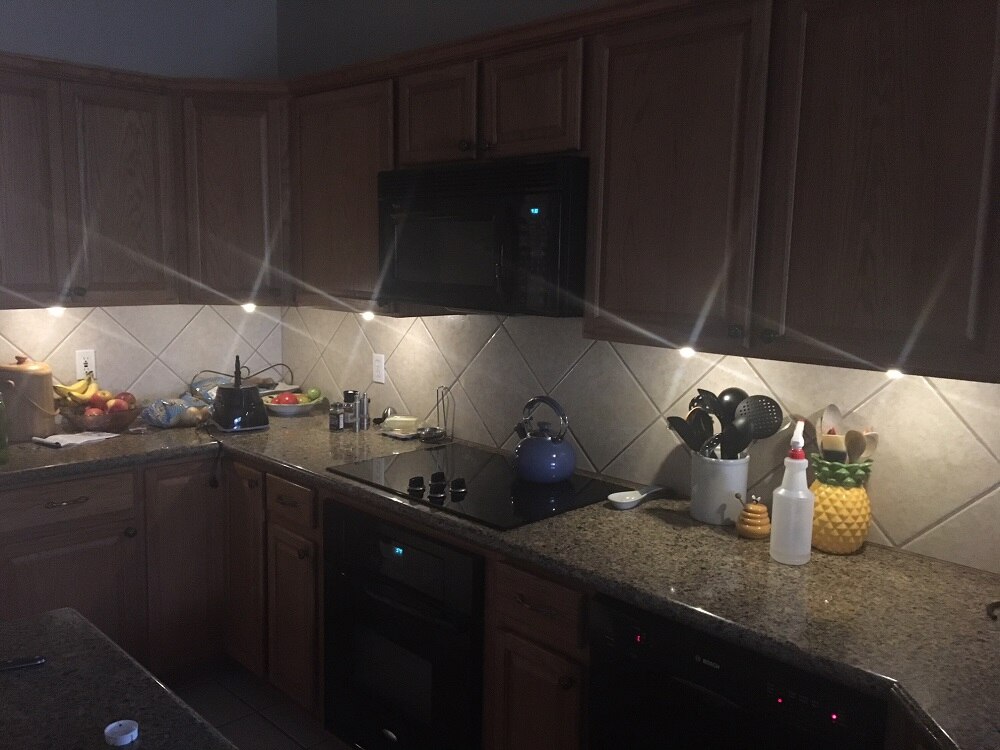
Speaking of light intensities, I did some simple light measurements in the kitchen, over several different light conditions (morning, afternoon and evening) to better understand the effectivity of my current lighting system.  These measurements were taken below each of the under cabinet lights (approximately 18 inches away from the light) with four conditions (0 - ambient light, 1 - under cabinet lights only, 2 - overhead lights (LEDs) and 3 - all lights on).  The lights are numbered 1-5, starting in the left-hand corner, moving across the range and to the right-hand side of the picture above.  Note: The kitchen area does not have any direct windows, but is near the dining nook area which has a north facing windows.  Also, all lighting is filtered by multiple mature oak trees.


In the above graphs, the majority of the light at the work surfaces, is due to the overhead lights.  This does not show the full value of the under cabinet lights, as shadowing does occur while working at these positions (I purposely avoided shadowing of the light sensor during taking these measurements, but maybe I need to repeat these measurements while taking a uniform position, casting a shadow on the light meter?).


My goals for this project.


1) Qualify PIR motion detection by available light and/or time of day, i.e. don't add light if it is not really necessary. (Ambient light sensing and RTC)

2) Make light puck lighting more efficient and also adjustable, to add only the necessary amount of light. (Ambient light sensing and new case style)

3) Build a remote controlled, A/C mains switch to embed into the microwave oven to control its under unit lighting (or add a small transformer and a stripped down light puck). (Wireless transceiver - RFM69HCW)

4) Add a visible 'end of period' signal (flash or slowly decreasing light level) to signal the user so that you can create some motion to re-trigger the interval.

5) Add a simple way to make the system operate exactly like it does now so that I don't upset my wife, as she is perfectly happy with the system as it is now.


This is beginning to get a little exciting as I love having a new project to work on.


Gene

Anonymous

Top Comments

  • shabaz
    shabaz over 3 years ago +6

    Just to put this out there as an idea (and maybe to be prior art to show it is in the public domain, if anyone tries to patent it in future : ) since the PIR is being used to detect humans, then that means…

  • genebren
    genebren over 3 years ago in reply to shabaz +5

    Very interesting idea!  I do have a UV system attached to my A/C unit to act as an air purifier and I have a client that is using UV to purify water.  I can see that there is a well established use case…

  • danielw
    danielw over 3 years ago +4

    Nice project!  Using a PIR is a great idea.  I still have 20W Halogens that I've been saying I'll replace when they fail.  When they get left on in the kitchen, I walk in and count up 20W, 40W, 60W…

  • genebren
    genebren over 3 years ago in reply to aspork42

    James,


    That is very cool how you embedded the LEDs and the touch/light sensors into you back splash.  What a great idea.  If I ever re-tile the kitchen (which I would like to get around to) I would like to follow your lead and do something like this.  Thanks for sharing,


    Gene

    • Cancel
    • Up +1 Down
    • Reply
    • More
    • Cancel
  • aspork42
    aspork42 over 3 years ago

    This is awesome! I was /very/ close to adding PIR when I did my backsplash tile (video below) but IR light doesnt transmit through normal glass tile. I was going to embed the PIR sensor behind the tiles. In the end, I just embedded the LED strips, capacitive touch sensors, and one LDR photocell for sensing the lighting.


    You don't have permission to edit metadata of this video.
    Edit media
    x
    Upload Preview


    I will have to do a write up on this project at some point. I want to add a motion sensor in my kitchen to do just as you do as well. Here is an image of what the LDR reads out during a typical day (or at least this is what it read today).


    This readout is an OpenHab display (in a web browser) which I have running on a cheap-o tablet which sits on the kitchen counter - it can briefly be seen in the video.


    You can see the 'natural' changes in the lighting level and the plateaus where the normal kitchen lights went on and off.

    • Cancel
    • Up +4 Down
    • Reply
    • More
    • Cancel
  • genebren
    genebren over 3 years ago in reply to danielw

    Daniel,


    I was in love with Halogen lights for a long time (I still have ~ two dozen bulbs in the garage), that is until I did the same math.  That is a lot of Watts.  After replacing all of the overhead light with LEDs and noticing that I still had some shadows, I decided on the under cabinet LEDs.  Your question about speed and length on the I2C bus really got me thinking.  I have about 15' (~4.5m) of cable run at a clock rate of ~50kHz, which might be pushing it a bit.  I have not seen any indication of signal issues and the signals do look clean on the oscilloscope, but as I rework the system I might want to drop the clock rate a bit (maybe to 10kHz).


    Gene

    • Cancel
    • Up +1 Down
    • Reply
    • More
    • Cancel
  • danielw
    danielw over 3 years ago

    Nice project!  Using a PIR is a great idea.  I still have 20W Halogens that I've been saying I'll replace when they fail.  When they get left on in the kitchen, I walk in and count up 20W, 40W, 60W.... And think how much energy is being wasted.


    How long and fast is your I2C Bus?  I have never risked I2C other than on board comms thinking it is restricted to short distances.  (I've just read at 10Kbaud it's 10m)

    • Cancel
    • Up +4 Down
    • Reply
    • More
    • Cancel
  • three-phase
    three-phase over 3 years ago

    Interesting project, look forward to future updates.


    Kind regards.

    • Cancel
    • Up +2 Down
    • Reply
    • More
    • Cancel
>
Element14

element14 is the first online community specifically for engineers. Connect with your peers and get expert answers to your questions.

  • Members
  • Learn
  • Technologies
  • Challenges & Projects
  • Products
  • Store
  • About Us
  • Feedback & Support
  • FAQs
  • Terms of Use
  • Privacy Policy
  • Legal and Copyright Notices
  • Sitemap
  • Cookies

An Avnet Company © 2022 Premier Farnell Limited. All Rights Reserved.

Premier Farnell Ltd, registered in England and Wales (no 00876412), registered office: Farnell House, Forge Lane, Leeds LS12 2NE.

ICP 备案号 10220084.

Follow element14

  • Facebook
  • Twitter
  • linkedin
  • YouTube