


UPDATE 8 May 2019: New documentation at the end of the blog on replacing thermocouple amplifier with the Arduino MKR THERM SHIELD, the Arduino MKR RGB SHIELD, and further automation experiments.
Introduction
Element 14 provided me with an Arduino MKR WIFi 1010 on Arduino Day and it encouraged me to work on a project I have had in mind for some time. Soldering Surface Mount Devices (SMD) by hand is doable with large parts but the results are sometimes of lower quality and small parts are difficult. An easy next step is to modify a toaster oven for use as a reflow oven. This project describes how to get started with a basic setup and also adds the ability to monitor actual temperature on adafruit.io and compare it to the desired reflow profile in real time.
Features
- Low cost
- Easy to get started
- Faster than hand soldering
- Improved solder quality
Requirements
- Arduino MKR WiFi 1010Arduino MKR WiFi 1010
- Inexpensive toaster oven
- Thermocouple Amplifier and K-type Thermocouple
- adafriuit.io account
Background
Up until now I soldered SMD parts with an iron by hand or used a hot air rework station for some parts with an iron to remove solder bridges. This is time consuming and does not always give good results. In addition, things become much more difficult as parts get smaller. My comfort level for hand soldering passives is 0805 and TSSOP for packages. Recently I became interested in the MSP430FR2433 microcontroller which is only available in VQFN or DSBGA. Since BGA is not hand solderable I opted for QFN and was successful with the hot air gun only after ruining one part and multiple attempts which required removing and replacing the part (not good). It was time to upgrade to an oven.
There are a number of boards and projects that describe how to control the temperature profile with a microcontroller but I elected to start with manual control. My toaster oven was the cheapest one I could find at less than $30 and easily meets reflow temperature requirements for lead-free solder. Although some recommend convection heating my toaster oven does not have it. I used the procedure described by Andreas Spiess in this video (don't user your kitchen oven  as suggested at the end of the video).
Note: The procedures and methods described below are an improvement over the hand soldering I used previously where actual temperature and time were not controlled. They are presented here as a way to do prototyping and one off non-critical projects but are a long ways from production level equipment and processes.
Oven Modification
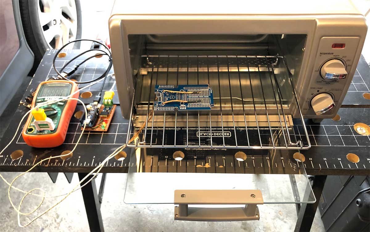
The oven is an inexpensive Black and Decker model placed in the garage as my lab space is limited. The garage also provides good ventilation. Two thermocouples are used in the setup - on for direct observation of temperature on the Extech multimeter at left and another attached to the MKR WiFi1010 reflow board which transmits to adafruit.io as described below. While some drill a hole in the side or top of the oven to insert thermocouples, I just snaked them through the bottom of the door near the hinge with no modification. The K-type tips were attached to a spare PCB for easy placement and more direct reading of PCB temperature. Reflow of the solder is observed through the window on the oven door.
Arduino MKR WiFi 1010 and Thermocouple Amplifier Breakout

A 5x7 cm single sided board was used to make a sturdy home for the Arduino MKR WiFi1010 and the thermocouple amplifier. Both are attached to female headers for easy removal if desired. The thermocouple amplifier is an inexpensive MAX6675 ordered sometime back from China (the MAX31855 is an upgraded part also available as a module - or make your own once you have a reflow oven). Three LEDs were added to make a simple user interface. The connections to the Arduino are listed in the comments of the firmware given below. The photo above has a stainless steel braided K-type thermocouple which I felt did not give as good of results as the Extech multimeter (read much lower) so another K-type thermocouple was fitted as shown below to a spare PCB.
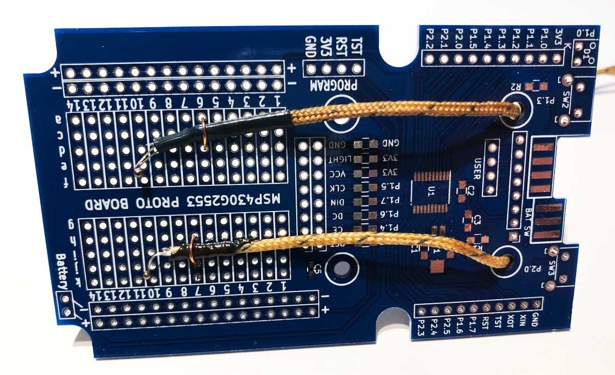
This arrangement allows the thermocouple to be closer contact to the PCB which should better reflect the actual temperature of the parts being reflowed.
Reflow Temperature Profile
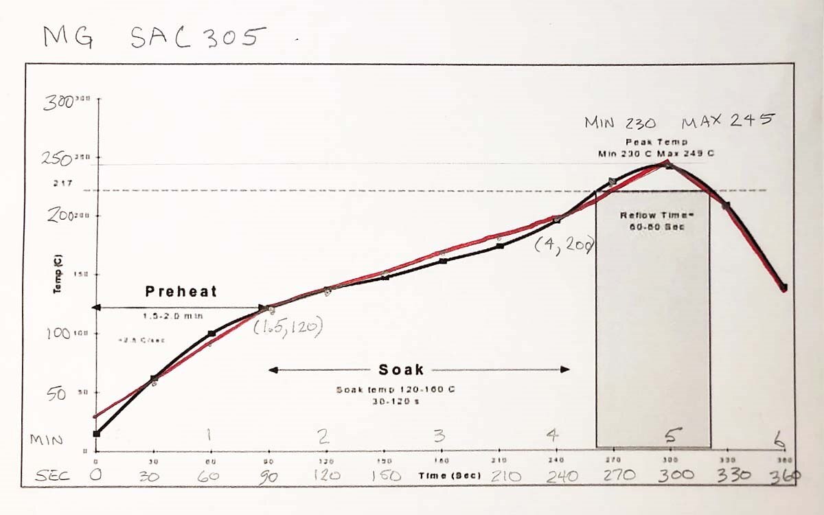
I am using MG Chemicals SAC305 solder, a lead-free paste. The annotated reflow profile from the datasheet is shown above. The black line is the recommended profile from MG Chemicals. Note in the comments that a range of times is allowed as well as a minimum and maximum during reflow and soak.
The red line is a series of straight lines user produced for inclusion in the firmware and meet the requirements of the datasheet.
Arduino MKR WiFi 1010 Firmware and adafruit.io
I elected to use the free version of adafruit.io to store the data and analyze it both in real time and after. No need to repeat the getting started process here as the tutorials by Adafruit are quite good. The resulting reflow profile as shown above looks quite nice. One complaint is that the settings for time windows is quite coarse (one hour minimum) so isolating reflow runs that are close together is not possible.
The Arduino IDE, version 1.8.4, was used to program the microcontroller. Adafruit provides an easy to use library for Arduino. However, I have been interested in learning more about the REST API, thinking that it might provide more control over adafruit.io. This turns out to not be the case as far as I can tell and I find the library easier to use but it was a good learning exercise.
Arduino.JSON was used to serialize the JSON documents sent to adafruit.io. It provides efficient serialization and deserialization for microcontrollers and I recommend it. I purchased the book that goes with for $10 which helped a lot since this was my first exposure to JSON.
The Adafruit MAX6675 library was used for the thermocouple. The firmware was hacked together quickly by an amateur (me :-) so be warned. It seems to work but I provide it with no guarantees or warrantees of any kind.
/*
 * reflowOven_ArduinoJSON_V4
 * Sends reflow oven information to adafruit.io
 * F Milburn  March 2019
 *
 * Requirements:
 * -------------
 *  - Arduino MKR WIFI 1010
 *  - MAX6675 and K-type thermocouple
 *  - account on adafruit.io
 *
 * Acknowledgement:
 * ----------------
 * JSON based on the work of Benoit Blanchon (see book chapter 4)
 *   https://arduinojson.org/book/
 *   https://arduinojson.org/
 * Arduino MAX6675 library by Adafruit
 */
#include <ArduinoJson.h>
#include <WiFiNINA.h>
#include <SPI.h>
#include "config.h"
#include "max6675.h"
// Pin Connections
const int redLed =    1;
const int yellowLed = 2;
const int greenLed =  3;
const int thermoDO =  4;
const int thermoCS =  5;
const int thermoCLK = 6;
// Debug levels
const int debug   =   0;              // 0 = no debug print
                                      // 1 = minimal, 2 = moderate, 3 = maximum
                                      // set to 0 when not connected to Serial
const char ssid[] =   WIFI_SSID;
const char pass[] =   WIFI_PASS;
MAX6675 thermocouple(thermoCLK, thermoCS, thermoDO);
enum reflowProfile{
  startHeat,
  preHeat,
  soak,
  startReflow,
  reflow,
  cool,
  finish,
  tail
} reflowIndex;
const int numProfiles = 8;             // must equal num members of enum reflowProfile
unsigned long reflowTemp[numProfiles];
unsigned long reflowTime[numProfiles];
void setup() {

  // Initialize Serial
  if (debug){
    Serial.begin(115200);
    while (!Serial);
  }
  // Initialize LEDs
  pinMode(redLed, OUTPUT);
  digitalWrite(redLed, LOW);
  pinMode(yellowLed, OUTPUT);
  digitalWrite(yellowLed, LOW);
  pinMode(greenLed, OUTPUT);
  digitalWrite(greenLed, HIGH);
  // Initialize WiFi
  int status = WL_IDLE_STATUS;
  if (debug) Serial.print("Attempting WiFi connection ");
  while (status != WL_CONNECTED){
    if (debug) Serial.print(".");
    status = WiFi.begin(ssid, pass);
    delay(1000);
  }
  if (debug) Serial.println("");

  // Connected
  if (debug > 1){
    Serial.println("WiFi connection successful\n");
    digitalWrite(greenLed, LOW);
    printCurrentNet();
    printWiFiData();
    Serial.println("");
  }
  // Test thermocouple
  if (debug > 1){
   Serial.print("MAX6675 C = ");
   Serial.println(thermocouple.readCelsius());
   Serial.println("");
  }
  // Define reflow profile
  reflowTime[startHeat] =    0;
  reflowTime[preHeat] =      90000;
  reflowTime[soak] =         150000 + reflowTime[preHeat];
  reflowTime[startReflow] =  20000 + reflowTime[soak];
  reflowTime[reflow] =       40000 + reflowTime[startReflow];
  reflowTime[cool] =         20000 + reflowTime[reflow];
  reflowTime[finish] =       40000 + reflowTime[cool];
  reflowTime[tail] =         240000 +reflowTime[finish];
  reflowTemp[startHeat] =    25;
  reflowTemp[preHeat] =      120;
  reflowTemp[soak] =         200;
  reflowTemp[startReflow] =  217;
  reflowTemp[reflow] =       245;
  reflowTemp[cool] =         217;
  reflowTemp[finish] =       150;
  reflowTemp[tail] =         25;
}
void loop() {

  // Allocate the JsonDocument to store this document:
  // {
  //   "feeds": [
  //     {
  //       "key": "reflow-profile",
  //       "value": 0.0
  //     },
  //     {
  //       "key": "reflow-temp",
  //       "value": 0.0
  //     }
  //   ]
  // }
  const int capacity = JSON_ARRAY_SIZE(2) + 4 * JSON_OBJECT_SIZE(2);
  StaticJsonDocument<capacity> doc;
  // Add the "location" object
  JsonObject location = doc.createNestedObject("location");
  location["lat"] = 47.5;
  location["lon"] = -122.4;
    // Add the "feeds" array
  JsonArray feeds = doc.createNestedArray("feeds");
  // Add the first feed"
  JsonObject feed1 = feeds.createNestedObject();
  feed1["key"] = "reflow-profile";
  feed1["value"] = 25;
  // Add the second feed"
  JsonObject feed2 = feeds.createNestedObject();
  feed2["key"] = "reflow-temp";
  feed2["value"] = 25;
  unsigned long eTime = 0;
  int i;

  while (eTime < reflowTime[tail]){
    unsigned int lowIndex = 0;
    int i;
    for (i = 0; i < numProfiles; i++){
      if (eTime > reflowTime[i]){
        lowIndex = i;
      }
    }
    if (lowIndex < startReflow){
      digitalWrite(yellowLed, HIGH);
    }
    else if ((lowIndex >= startReflow) && (lowIndex < cool)){
      digitalWrite(redLed, HIGH);
    }
    else{
      digitalWrite(yellowLed, LOW);
      digitalWrite(redLed, LOW);
      digitalWrite(greenLed, HIGH);
    }
    float reflowT, xmin, ymin, xmax, ymax;
    xmin = reflowTime[lowIndex];
    ymin = reflowTemp[lowIndex];
    xmax = reflowTime[lowIndex+1];
    ymax = reflowTemp[lowIndex+1];
    reflowT =  ymin + ((eTime - xmin) / (xmax - xmin)) * (ymax - ymin);
    if (debug > 2){
      Serial.print("lowIndex = ");
      Serial.println(lowIndex);
      Serial.print("xmin = ");
      Serial.print(xmin);
      Serial.print("         xmax = ");
      Serial.println(xmax);
      Serial.print("ymin = ");
      Serial.print(ymin);
      Serial.print("         ymax = ");
      Serial.println(ymax);
      Serial.print("eTime = ");
      Serial.print(eTime);
      Serial.print("        reflowT = ");
      Serial.println(reflowT);
    }
    feed1["value"] = reflowT;

    // Update the second feed"
    feed2["value"] = thermocouple.readCelsius();

    if (debug) Serial.println("Sending to io.adafruit.com...");
    if (debug > 1){

    }

    // Connect to the HTTP server
    WiFiClient client;
    client.setTimeout(10000);
    if (!client.connect("io.adafruit.com", 80)) {
      if (debug) Serial.println("Connection failed");
      return;
    }
    // Send the first line of the request
    client.println(
        "POST /api/v2/" IO_USERNAME "/groups/" IO_GROUP "/data HTTP/1.1");

    // Send the HTTP headers
    client.println("Host: io.adafruit.com");
    client.println("Connection: close");
    client.print("Content-Length: ");
    client.println(measureJson(doc));
    client.println("Content-Type: application/json");
    client.println("X-AIO-Key: " IO_KEY);

    // Terminate headers with a blank line
    client.println();

    // Send the JSON document in body
    serializeJson(doc, client);

    // Check the  HTTP status (should be "HTTP/1.1 200 OK")
    char status[32] = {0};
    client.readBytesUntil('\r', status, sizeof(status));
    if (strcmp(status + 9, "200 OK") != 0) {
      if (debug) Serial.print("Unexpected status: ");
      if (debug) Serial.println(status);
      return;
    }

    // Close the connection
    client.stop();
    if (debug) Serial.println("OK!");
    delay(5000);
    eTime += 5000;

  }
  digitalWrite(greenLed, LOW);
  while(true);                                                    // stop forever
}
void printWiFiData() {
  // print WiFi shield's IP address:
  IPAddress ip = WiFi.localIP();
  Serial.print("IP Address: ");
  Serial.println(ip);
  // print MAC address:
  byte mac[6];
  WiFi.macAddress(mac);
  Serial.print("MAC address: ");
  printMacAddress(mac);
}
void printCurrentNet() {
  // print SSID of the network:
  Serial.print("SSID: ");
  Serial.println(WiFi.SSID());
  // print MAC address of the router:
  byte bssid[6];
  WiFi.BSSID(bssid);
  Serial.print("BSSID: ");
  printMacAddress(bssid);
  // print received signal strength:
  long rssi = WiFi.RSSI();
  Serial.print("Signal strength (RSSI):");
  Serial.println(rssi);
  // print encryption type:
  byte encryption = WiFi.encryptionType();
  Serial.print("Encryption Type:");
  Serial.println(encryption, HEX);
  Serial.println();
}
void printMacAddress(byte mac[]) {
  for (int i = 5; i >= 0; i--) {
    if (mac[i] < 16) {
      Serial.print("0");
    }
    Serial.print(mac[i], HEX);
    if (i > 0) {
      Serial.print(":");
    }
  }
  Serial.println();
}
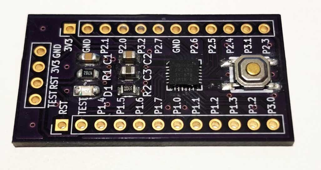
Preparing the PCB
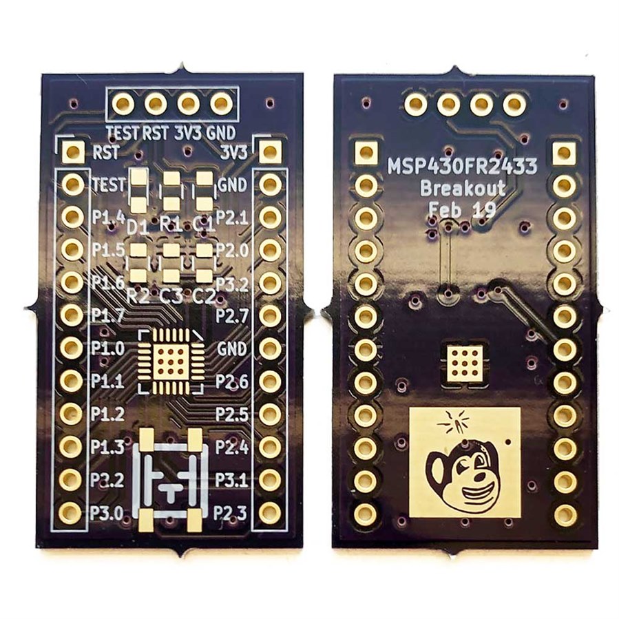
For the first test a modified version of the KiCad designed MSP430FR2433 breakout PCB described here and shown above was used. I originally had problems soldering the VQFN package by hand but was eventually successful with the hot air gun. One of the flaws in the PCB design was there were no vias in the copper pad in the center of the package. For this latest version nine vias were added to the center which connect to the ground plane on the back side. A cartoon mouse with a thought LED going off was also added because, well just because. KiCad does not do a designs rule check if graphics are printed on the copper layer so be careful with that.... In this case everything works fine.
The pads were cleaned with alcohol first. Solder paste was applied with a toothpick since I did not get a stencil made. Unfortunately there is no photo, but it was a pretty ugly job. I was careful not to get too much paste on the ground pad of the MSP430 but it is necessary to add paste there in order to get good heat transfer and for mechanical strength. The PCBs were made by OSH Park and there is solder resist between VQFN package pins and ground - some board houses, including the inexpensive one I typically use in China, will not meet the specification required for solder resist this tight unless additional money is paid.
Using the Reflow Oven
The procedure for using the oven and the user interface are simple. To start the reflow, give power to the MKR WiFi1010 and turn the toaster oven to about 30 deg. F 300 deg. F (the controls on my oven are in Fahrenheit. You will have to experiment with your particular oven - temperature control on mine was not that accurate - another approach is to turn the oven all the way on and then manually off before it hits the desired temperature). The green LED will flicker every 5 seconds as a message is sent to adafruit.io. The primary use of the LEDs is to indicate which phase the reflow oven is in as shown in the table below:
| LED status | Phase | Oven Control |
|---|---|---|
| Green flickers, Yellow on, Red off | Preheat / Soak | 300 deg. F |
| Green flickers, Yellow on, Red on | Reflow | Turn all the way up but don't exceed 245 deg. C - watch for reflow |
| Green flicker, Yellow off, Red off | Cool | Turn it off and open the door |
Reflow Temperature Profile
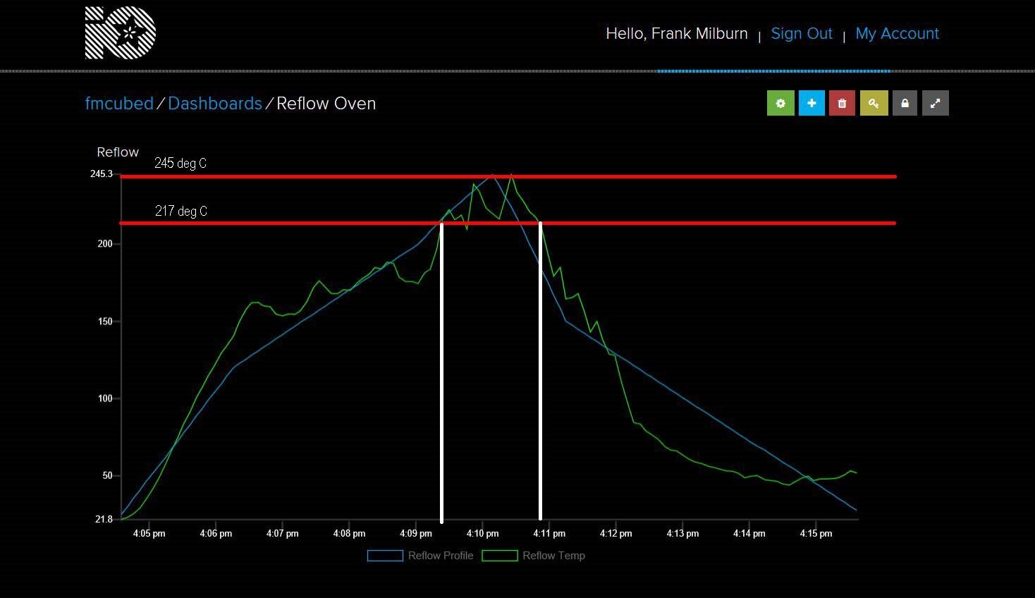
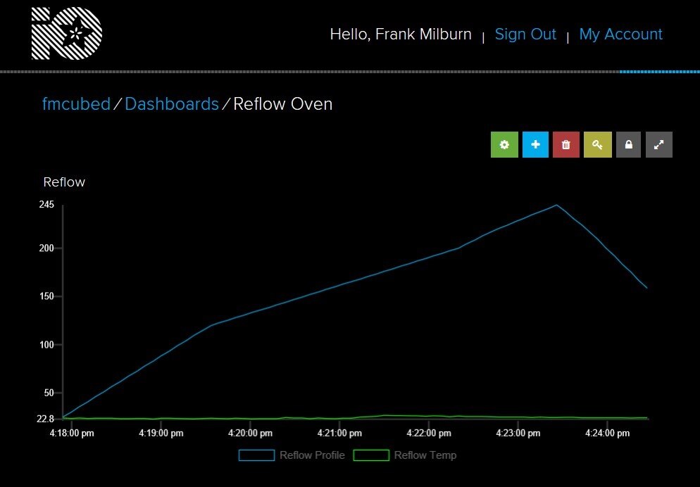
Above is the adafruit.io dashboard from the very first attempt to use the reflow oven with some added annotation.
- Blue line is the target reflow profile
- Green line is actual reflow
- Red lines were added and are the temperature limits for the reflow stage
- White lines were added and is the time it was in the reflow stage
The soak temperature is not critical and both time and temperature are acceptable. With the exception of one 5 second interval near the beginning of the reflow where temperature dropped a tiny bit below the desired level it is OK. The length of time is longer than the profile in the firmware (as I was not watching closely) but within the datasheet specification. Given that it is a bit longer, the temperature anomaly mentioned is also OK. All in all, not bad with opportunity to improve with experience.
Results
Whoops, got a bit too much solder on some of those pads but not bad for the first attempt without a stencil. I did have to remove a short bridge on one side of the VQFN but it cleaned very easily in one pass. But does it work? First time! Below is a video recap and the new board blinking hello world:
I am pleased with the way this turned out and it was relatively quick and easy. Regarding improvements, adding a buzzer when reflow zones change would be good. I have some experience with process control and could add PID control using a relay. But given the small number of SMD PCBs I solder it probably would not be worth the effort.
Thanks to Element14 for providing the Arduino MKR WiFi1010 and the Arduino Day activities. As usual comments and suggestions are appreciated.
8 May 2019 Updates
ARDUINO MKR THERM SHIELD
Element14 (Thanks Tariq!) has provided me with an Arduino MKR THERM SHIELD which is an upgrade over the thermocouple amplifier I was previously using and is an easy replacement. In the photo below the old board is shown upper left and the shield installed on the MKR WiFi 1010 below it. The existing thermocouple plugs easily into it.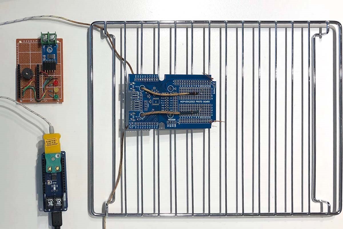
Modifying the code is also easy. Include the new library:
#include <Arduino_MKRTHERM.h>
Start the shield up in setup():
  if (!THERM.begin()) {
    Serial.println("Failed to initialize MKR THERM shield!");
    while (1);
  }
Replace the calls to thermocouple.readCelsius() with calls to THERM.readTemperature(), e.g.
   // feed2["value"] = thermocouple.readCelsius();
   feed2["value"] = THERM.readTemperature();
The code works the same as before.
ARDUINO MKR RGB SHIELD
I had hoped to use the MKR RGB SHIELD to display temperature and other information but unfortunately there is a conflict between that shield and the MKR THERM SHIELD - The temperature reads 0.00 when the RGB shield is being used :-(. I did not have time to dig into this but to be honest the IOT display on my tablet is more useful so it is not a required addition.
Nonetheless, the RGB SHIELD is easy and fun to use and I expect to use it on other projects. Here is a demonstration of fixed and scrolling text based on the example in the Arduino library.
Edits and Corrections
23 March 2019: Corrected typo in section on Using the Reflow Oven and added clarification.
Top Comments