


 | Enter Your Project for a chance to win a Maker Tool Kit, an Oscilloscope Grand Prize for the project that brings the Most Joy to the Heart, and Gift to Gives! | Project14 Home |
| Monthly Themes | ||
| Monthly Theme Poll |

Updated I have re-formatted this blog to take advantage of some the advanced formatting features - hopefully it reads much better!
Project Overview
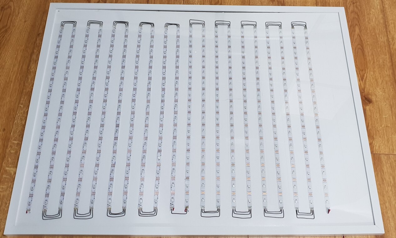
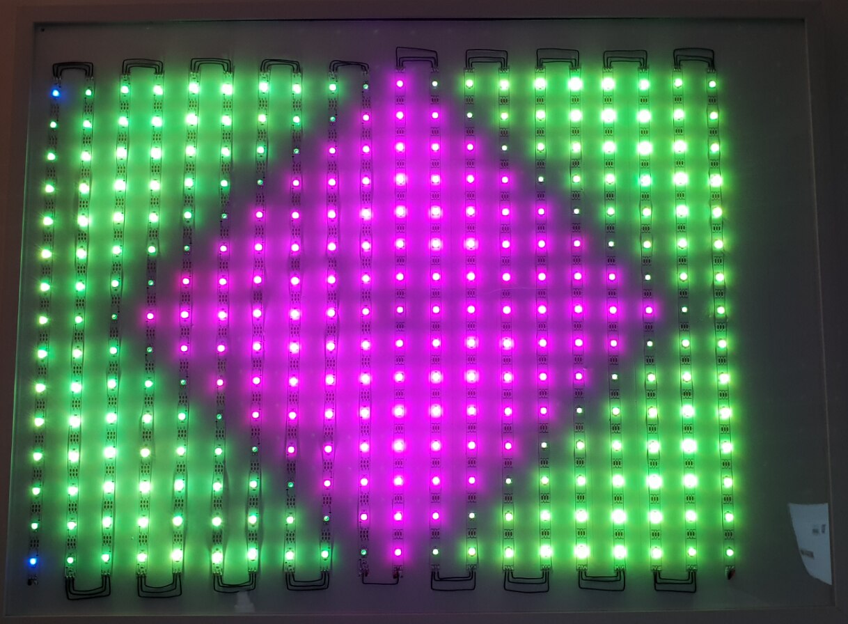
I have always been fascinated by LED displays and the effects that can be produced. Over the last few years multi colour programmable LED's such as Neopixels, WS2812B LEDs etc seem to have become very popular and with the ever increasing amount of cheap development kits on the market it has become a lot more reachable for a hobbyist to create some pretty cool projects with LED's! So I decided to build an LED matrix picture frame with an mbed LPC1768 board and 10m of WS2812B LED strip. I have programmed the LPC1768 board to use Art-Net so that I can send data to the matrix from my laptop using Madrix or Glediator software. Although this is not the most creative LED project, I am still pretty pleased with it!
Project Videos
Project Pictures
| {gallery} Flashy Picture Frame |
|---|
LED Frame Overview |
|
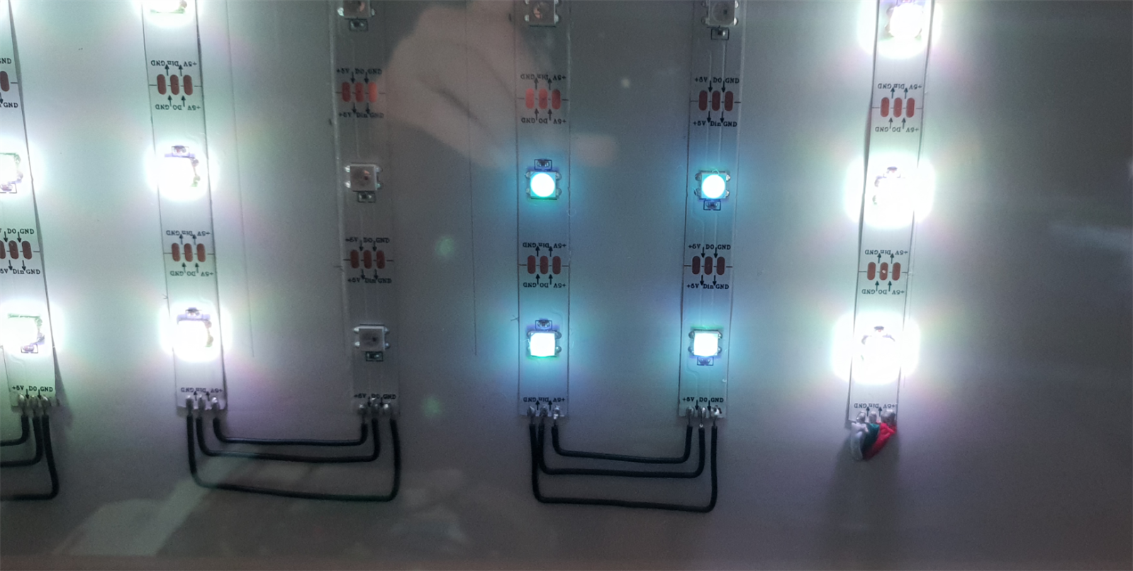
Close up of connections |
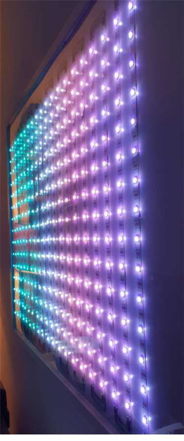
Side view |
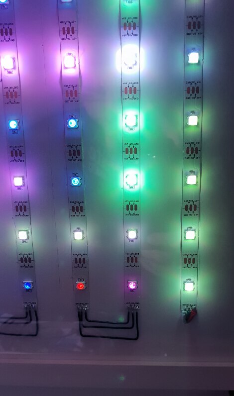
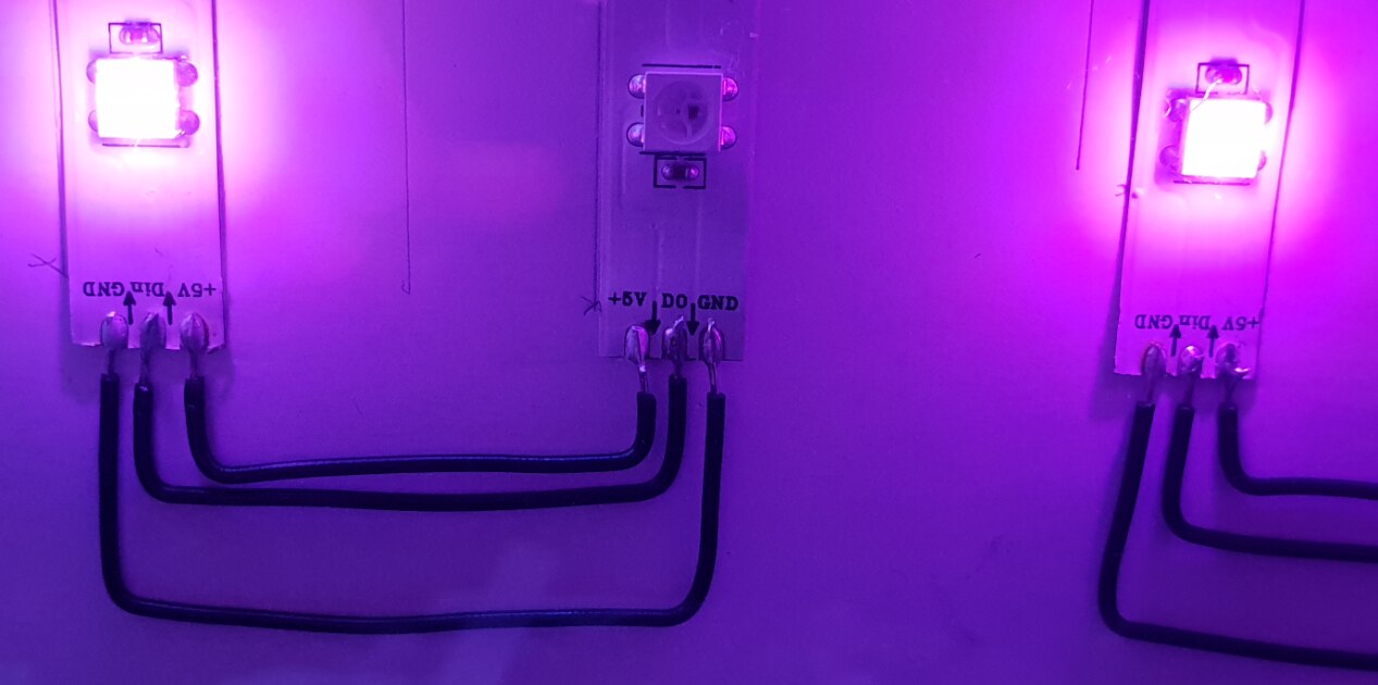
Close up |
Close up |
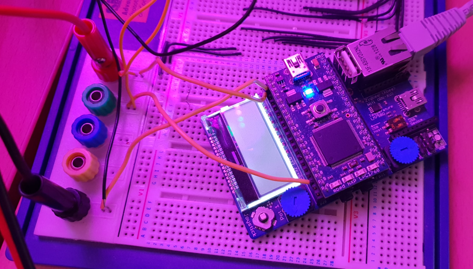
mbed LPC1768 control board |
Full set up - note the laptop is only connected via WiFi |


| {tabbedtable} Tab Label | Tab Content |
|---|---|
| Parts List | Parts List
|
| Construction | Construction
Construction for this project was pretty straight forward, although quite time consuming!........
5. Then, I taped the wires down on the back of the board and routed them to the bottom right hand corner. 6. Finally I mounted the A1 Foamex board inside the frame, assembled it and then connected the power and data connections to the mbed application board and bench top PSU. |
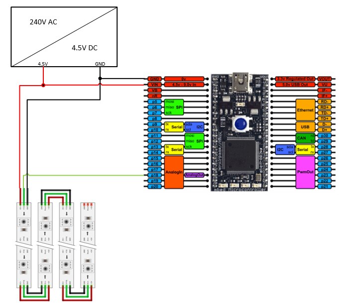
| Connections | ConnectionsConnecting up to WS2812B LEDs is pretty straight forward. I have a pretty basic bench PSU with only a selection of voltages (A descent bench top PSU is definitely on my future shopping list!) For this project I am using 4.5V as this allows me to feed power to the mbed board and WS2812B LEDs whilst also allowing me to connect the 3.3V data signal from the mbed board to the LEDs without needing a level shifter - as the data pin voltage should be no less than 70% of the supply voltage to the LEDs. I could get away with up to about 4.7V. This is not really good practice, but I can get away with it on this. The only other connection then, is the data pin - for this I have used pin 18 of the board which is connected to one end of the strip. It is important that this is connected to the input end of the strip which is marked with an arrow.
|
Software
So this is the really important part of this project and the part that took me the most time. Most of the code I have found from within the maker community and so for the most part it was a matter of piecing it together. The code on the mbed module is written in C++ on the mbed online compiler. The two software packages I have used on the PC to send data to the matrix are Madrix and Glediator. I will go into these in more detail further down.
Main MCU Program
As I am using the mbed LPC1768 (which is a great little board!) I have utilised the online mbed IDE which is part of the arm mbed system. The programming language used is C++.
Here is how the mbed complier looks:

The libraries that are available for mbed enabled devices are fantastic - the level of abstraction makes it very easy for a novice programmer to get going easily. There is a very well documented API on the mbed website. As an example, to toggle an on board LED, you just need the following code:
//Toggle an LED
#include "mbed.h"

DigitalOut led (LED1);

int main(){
    while(1){
        led = !led;
        wait(0.2);
    }
}
This is very similar to the Arduino in that a lot of the low level code to control the hardware registers, clock set up and MCU set up is done for you.
Another big plus for this board and any board that is mbed enabled is the mbed community - there is so much code available that it is likely that someone will have done at least part of what you are trying to do already. All code developed on the mbed portal is stored in a git type repository.
So my plan was to make my LED picture frame controllable from my laptop and ideally through Ethernet rather than USB or any other direct connection. After doing a bit of digging around the internet, I came across Art-Net.
Art-Net is basically a protocol for delivering DMX512 data over ethernet. For anyone unfamiliar with DMX, it is a protocol used to send control data to stage lighting and equipment. This Wikipedia article gives a good description.
The other critical part of the software was to actually control the LEDs! WS2812B LED's have a very strict timing specification to work properly. There are different methods that I have seen used - utilising an on-board PWM controller or bit-banging seem to be the most common.
Luckily for me, I managed to find substantial portions of code for both Art-Net and WS2812B LED control. You can read many articles on the internet on WS2812B LEDs - for example on Sparkfun or Adafruit. There are also many more articles out there.
I will now jump into a bit more detail on the two main elements of the code:
| {tabbedtable} Tab Label | Tab Content |
|---|---|
| Art-Net Overview | Art-Net OverviewArt-Net is a protocol that has been developed by Artistic License as a way to carry DMX512 and RDM data over an Ethernet network. It uses UDP rather than TCP to communicate between a node and controller. Artistic-License have published the specification and made it available for anyone to use on a royalty-free basis. I decided it was the ideal protocol for this project for the following reasons:
I have based my program on the example found on the mbed community but have adapted it as the example was set to take Art-Net data and re send it over RS485 as DMX512. It also used an older version of the Ethernet Interface library and did not use a Real Time OS.
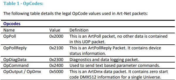
For my implementation, I have only used the parts of the Art-Net protocol to make my project work: |
| ArtPoll Packet | ArtPoll Packet
The program on my PC will initially send an OpPoll message with the OpCode 0x2000 and then my mbed device will respond with an OpPollReply message with the OpCode 0x2100. These two packet types used are defined as structs in the ArtNet.h header file:
struct ArtPoll_Packet {
     char ID[8];
     unsigned short OpCode; // 0x5000
     unsigned char VersionH; // 0
     unsigned char Version; // 14
     unsigned char TalkToMe; // 0
} __attribute__((packed));


// a responce to a artpoll packet
struct ArtPollReply_Packet {
     char ID[8];
     unsigned short OpCode; // 0x2000
     struct ArtAddr Addr; // our ip address and UDP port
     unsigned char VersionH;
     unsigned char Version;
     unsigned char SubSwitchH;
     unsigned char SubSwitch;
     unsigned short OEM;
     char UbeaVersion;
     char Status;
     unsigned short EstaMan;
     char ShortName[18];
     char LongName[64];
     char NodeReport[64];
     unsigned char NumPortsH;
     unsigned char NumPorts;
     unsigned char PortType[4];
     unsigned char GoodInput[4];
     unsigned char GoodOutput[4];
     unsigned char Swin[4];
     unsigned char Swout[4];
     unsigned char SwVideo;
     unsigned char SwMacro;
     unsigned char SwRemote;
     unsigned char Spare[3]; // three spare bytes
     unsigned char Style;
     unsigned char Mac[6];
     unsigned char Padding[32]; // padding
} __attribute__((packed));
The default values for the ArtPollReply packet are defined in a function - InitArtPollReplyDefaults() that is called at program startup: void InitArtPollReplyDefaults () {
memcpy(ArtPollReply.ID, ArtHeaderID, 8);
ArtPollReply.OpCode = OP_PollReply; // reply packet
ArtPollReply.Version = ArtVersion;
memcpy(&ArtPollReply.Addr, &localaddr, sizeof(localaddr));
strncpy(ArtPollReply.ShortName, STR_ShortName, 18);
strncpy(ArtPollReply.LongName, STR_LongName, 64);
strncpy(ArtPollReply.NodeReport, "OK", 64);
ArtPollReply.Style = StyleNode;
mbed_mac_address((char*)&ArtPollReply.Mac);
ArtPollReply.NumPortsH = 0;
ArtPollReply.NumPorts = 2;
ArtPollReply.Swout[0] = 1;
ArtPollReply.Swout[1] = 2;
ArtPollReply.Swout[2] = 0;
ArtPollReply.Swout[3] = 0;
ArtPollReply.Swin[0] = 0;
ArtPollReply.Swin[1] = 0;
ArtPollReply.Swin[2] = 0;
ArtPollReply.Swin[3] = 0;
ArtPollReply.GoodOutput[0] = 0;
ArtPollReply.GoodOutput[1] = 0;
ArtPollReply.GoodOutput[2] = 0;
ArtPollReply.GoodOutput[3] = 0;
ArtPollReply.PortType[0] = 0x40; // bit7:Can output from Art-Net network, bit0-5: 0 - type = DMX512
ArtPollReply.PortType[1] = 0x40;
ArtPollReply.PortType[2] = 255;
ArtPollReply.PortType[3] = 255;
}
There are also a few constants that are defined in the header file: #define ArtMaxUniv 4 // Universe #define SizeRecvBuffer 700 #define ArtHeaderID "Art-Net" // packet header #define ArtUDPPort 0x1936 // UDP port 6454 for Art-Net #define ArtVersion 14 // Art-Net version #define OP_Output 0x5000 //Art-Net DMX Packet 'Output' #define OP_Poll 0x2000 // ArtPoll #define OP_PollReply 0x2100 // ArtPoll Reply #define StyleNode 0 #define StyleServer 1 #define STR_LongName "Art-Net to WS2812B - By Tony Beck" #define STR_ShortName "MBED ArtNet LED" |
ArtDMX_Packet | ArtDMX_Packet
// dmx transport packet
struct ArtDMX_Packet {
     char ID[8];
     unsigned short OpCode; // 0x5000
     unsigned char VersionH; // 0
     unsigned char Version; // 14
     unsigned char Sequence; // 0
     unsigned char Physical; // 0
     unsigned short Universe;
     unsigned short Length; // size of data segment
     unsigned char Data[512]; // data segment
} __attribute__((packed));
|
| WS2812B LED Control | WS2812B LED Control
So thankfully this was a bit easier as I did not really have to modify the code. I found a library on the mbed community written by Allen Wild that is specifically for the LPC1768 board. This library has a section written directly in assembly code due to the precise timing required for these LEDs. The library is very easy to use. You simply declare a NeoStrip object with the Data pin used and number of LEDs as parameters: NeoStrip strip(DATA_PIN, LED_COUNT);
In my code I have defined DATA_PIN and LED_COUNT at the head of my program: #define DATA_PIN p18 #define LED_COUNT 300
To set a value for the Red, Green and Blue elements of a Pixel, you just call the function SetPixel with the parameters p (pixel address) red value, green value and blue value: /** * Set a single pixel to the specified color, with red, green, and blue * values in separate arguments. */ void setPixel(int p, uint8_t red, uint8_t green, uint8_t blue);
Here is the code I have written to populate the data in the NeoStrip object: if(ArtDMX.Universe == 1)
{
for (pos = 0;pos<170;pos++)
{
byteLoc = (pos*3);
strip.setPixel(pos, RecvByte[8+byteLoc],RecvByte[9+byteLoc],RecvByte[10+byteLoc]);
// printf("%d, ",RecvByte[8+pos])
}
}
if(ArtDMX.Universe == 2)
{
for (pos = 170;pos<300;pos++)
{
byteLoc = ((pos-170)*3);
strip.setPixel(pos, RecvByte[8+byteLoc],RecvByte[9+byteLoc],RecvByte[10+byteLoc]);
}
}
// strip.write();
break;
Finally to actually send the data to the strip, the write() function has to be called. In my program, as I am using a Real Time Operating System, I call this in a separate thread every 10ms. void thread1(void const *args)
{
while(true)
{
/* static float dh = 360.0 / LED_COUNT;
static float x = 0;
for (int i = 0; i < LED_COUNT; i++)
strip.setPixel(i, hueToRGB((dh * i) - x));
x += 1;
if (x > 360)
x = 0;*/
strip.write();
Thread::wait(10);
}
}
One note I will add is that NeoStrip is the name that Adafruit use for these type of LED strips. |
| Ethernet Stack | Ethernet Stack
There is another 3rd part of the code that is equally important and on which the Art-Net library relies on and that is the EthernetInterface library.
This library provided by mbed has developed somewhat over the years. For this project, I used a newer version of the library than that used in the original code I based my program on. There were a few fundamental changes including adding reliance on an RTOS and changes in how you define the IP address settings. This is something that took me a while to figure out!
The library is based on the IwIP stack that has been designed as a lightweight TCP/IP stack for microcontrollers.
This project sets the device up as a UDP socket server which allows the program running on my laptop to bind to it. Art-Net uses UDP port 0x1936, so the programs starts by listening for incoming connections on this port.
For my project I have used a static address as then I don't need to adjust the set up on the software on my laptop. Only thing I have to watch for is that the static address I have used is not assigned to another device by my DHCP server!
The Art-Net specification is fairly specific on how the IP address should be configured when using static addressing. It states that the address should be a class A address derived from the MAC address of the node. As I am only using my project at home and not commercialising it, I have just set the address to a class D address in the same subnet as my existing network..... 192.168.1.130. This means I do not have to mess about with my laptop IP address settings. The software still works fine although I do get an error message in Madrix.
The IP settings are assigned to some const arrays at the start of my code: const char *ipAddr = "192.168.1.130"; const char *snMask = "255.255.255.0"; const char *gwAddr = "192.168.1.254";
The code to initialise the Ethernet Stack is:
  EthernetInterface eth;
#ifdef STATIC
    eth.init(ipAddr,snMask,gwAddr); //Use DHCP
#else
    eth.init();
#endif
    eth.connect();
    printf("\r\nIP Address is %s\r\n", eth.getIPAddress());
Note, I have left code in place to use DHCP if I did not define STATIC.
Next, to set up the UDP server and recieve data: UDPSocket server;
server.bind(ECHO_SERVER_PORT);
server.set_broadcasting();
Endpoint client;
char *RecvByte;
char buffer[1500];
int n = server.receiveFrom(client, buffer, sizeof(buffer));
buffer[n] = '\0'; |
PC Programs
So the final part of my project was to set up the programs on my laptop to send Art-Net data. The two programs I have used as mentioned above are Madrix and Glediator.
Glediator has a big advantage that it is free to use although not open source. It is based on java and so needs an up to date version the Java Runtime Environment installed. For a free program, it is actually very good!
Madrix is a full professoinal grade LED lighting control software made for the industry and has a price tag to match! It is very powerful and can produce some awesome displays......some of which I can only wish to work on!
Madrix
Thankfully for me, you can run Madrix in demo mode which has a few limitations. One of the main limitations is that the output will go off for a short time at random intervals. It will also stop its output after about 20 minutes. You then have to restart it.
I have used version 3.6 as the newer version 5 does not give any Art-Net output at all in Demo mode. Here is the download link.
| {gallery} Madrix |
|---|
Here is the GUI that you are presented with |
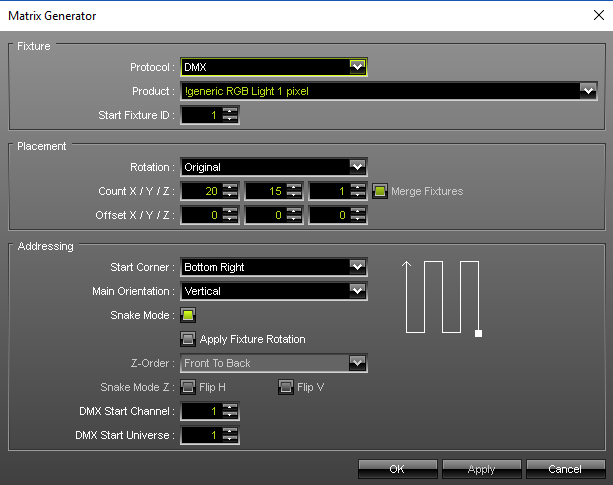
To set up initially, you need to set up the matrix dimensions and the actual device. You then have to patch all each pixel to an address |
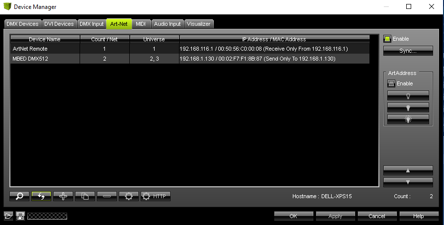
This is the display to set up the mbed module as an Art-Net device |
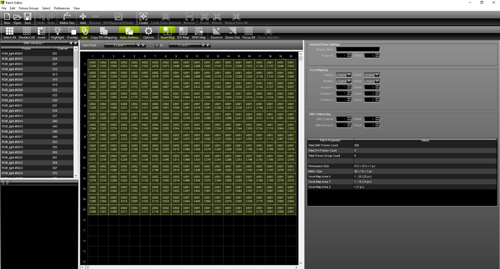
This is the view of the patch editor |
This is the tool to automatically assign each channel according to how the strips are wired |


Glediator
Glediator has been written by a couple of guys to control LED matrix and strips. The link to their website - solderlab.de is here. As I mentioned above it is free to download and use. It is not as advanced as Madrix but, it is still pretty cool and can make some great effects!
As it does not have as many features, it is easier to use! The only tricky part was the initial set up.
| {gallery} Glediator |
|---|
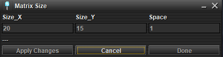
The first part is to set the matrix size |
Then set up some basic settings for the output |
and finally patch the LEDs to their corresponding address |


Conclusion
I have found this a really fun an interesting project to do! I learned a lot on the way..... before I undertook this project, I had very basic knowledge of DMX512 and no knowledge at all of Art-Net. There are a few improvements and upgrades I would like to make in the future as time, money and knowledge allows:
- Tidy up the code - make better use of pointers. I am sure the code could be made much more efficient and elegant.
- Make a bigger matrix with a finer pitch. You can get strips with 60 and even 120 LED's per meter. There will be a limitation on the LPC1768 to how many LED's it can drive, although with Art-Net you are not restricted to 1 controller.
- Paint the Foamex board black and use black LED strip.
- Use some kind of diffuser to spread the light better.
- Make a 3D type display!
If you have got to here, thanks for reading through my project! I hope this is interesting and informative and welcome any comments whether good or bad!
Code Link
If you want to check my code out on the mbed website, you can follow this link.
It is not the best code and there are still a lot of fragments left in from development...... but it works! 
------------------------------------------------------------------------------------------------------------------------------------------
Tony
Top Comments