


Semi-automated Plant Irrigation System
Summary
This is an automated system for watering my olive tree.
The main components are:
- A soil moisture sensor
- A 10 gallon bucket of water with a water level sensor
- An Adafruit Feather HUZZAH ESP8266 microcontroller (hereafter referred to as “feather”)
- A peristaltic water pump
The two sensors are connected to inputs of the feather, and the water pump is controlled by an output signal from the feather. There are two built in LED’s on the feather:
- Red: used to indicate that the soil is dry enough to warrant watering
- Blue: Used to indicate that the bucket is empty (requires a refill of water)
There are three criteria which all have to be met in order to turn on the pump (and water the plant):
- There must be water in the bucket
- The lack of moisture in the soil must be greater than a specified threshold value
- A specified minimum amount of time must have elapsed since the pump was last turned off while watering.
Any one of the following criteria will cause the pump to be turned off:
- No water left in the bucket
- The moisture level of the soil is higher than a specified threshold value (this criteria also triggers starting of the timer which keeps track of the amount of time that has elapsed since the pump was turned off).
Basically, the feather just goes in a loop checking the criteria above and taking the necessary action. Each loop iteration takes approximately 20-30 seconds to complete.
A feature that I would also like to implement is to have the system send me a message whenever it detects that the water bucket is empty (and possibly send a new reminder each day for a week before giving up). Unfortunately I have not found any official libraries with SMTP capabilities that I can use to accomplish this, so I do not know when or if I will be able to accomplish this goal.
I have tested the system quite a bit while implementing it (during the last 2 days) and feel confident that I have found and fixed all of the problems I have encountered along the way, but experience has taught me that the test of time is a very important test – and that test has only just begun.
Parts used
- 1 Adafruit Feather HUZZAH ESP8266 (https://learn.adafruit.com/adafruit-feather-huzzah-esp8266/overview)
- 1 5v 2.1A DC power supply w/micro usb contact (for the HUZZAH)
- 1 12v 1A DC power supply (https://www.kjell.com/no/produkter/elektro-og-verktoy/stromforsyning/stromforsyning/ac-dc/fast-utgangsspenning/ac-dc-stromadapter-12-v-(dc)-12-w-p44382)
- 1 power jack for the 12v power supply
- 1 soil moisture sensor (https://www.kjell.com/no/produkter/elektro-og-verktoy/arduino/moduler/luxorparts-jordfuktmaler-p87941)
- 1 water level switch NC (https://www.kjell.com/no/produkter/elektro-og-verktoy/elektronikk/electromechanics/strombrytere/nivabrytere/nivastrombryter-nc-p36037)
- 1 22k ohm 1/8w resistor
- 2 10k 1/8w resistor
- 1 33 ohm 1/4w resistor
- 2 1N4001 diodes
- 1 Peristaltic Pump (https://www.kjell.com/no/produkter/elektro-og-verktoy/elektronikk/electromechanics/motorer/luxorparts-vaeskepumpe-peristaltisk-p90782)
- 1 VR05R241A single pole DIL relay (https://www.kjell.com/no/produkter/elektro-og-verktoy/elektronikk/electromechanics/releer/1-polet-dil-rele-5-v-dc-0-5-a-30-v-p36110)
- 1 Breadboard
- Assorted jumper wires
Schematic Drawing

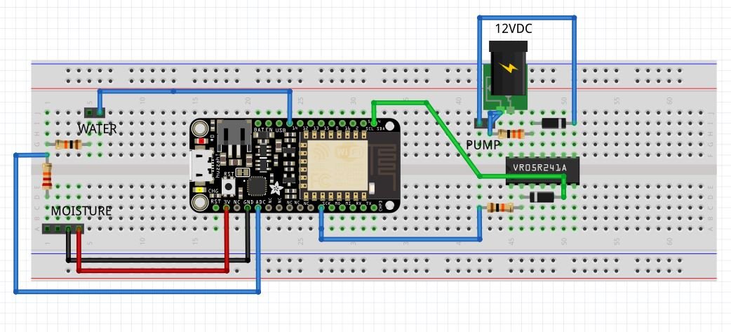
Breadboard
Code
#include

//==========
// CONSTANTS
//==========

// wifi
const char* MY_SSID     = "";
const char* PASSWORD = "";

// I/O
const int LED = 0;  // (Output) indicates pump status (pump ON => LOW signal => lit)
const int PUMP = 4; // (Output) turns water pump on (set LOW) and off (set HIGH)
const int WATER_EMPTY_LED = 2;  // (Output) indicates water reservoir status
                                // (empty => LOW signal => lit)
const int WATER_LEVEL = 14;  // (Input) to detect water in reservoir (water => HIGH)

// A0 : ADC (Analog Input) used to read soil humidity: high value => dry, low value => wet
// Max value is approx. 825 - bone dry
// Min value is approx. 470 - drowning in water
const int PUMP_ON_THRESHOLD = 700;  // ADC input value >= this value => Turn on water pump
const int PUMP_OFF_THRESHOLD = 650; // ADC input value <= this value => Turn off water pump
                                    // (and do not turn on again for at least a day)
const long MINIMUM_TIME = 1000 * 60 * 60 * 24; // minimum time between watering (1 day)

//==========
// VARIABLES
//==========

// timing
unsigned long previousMillis = 0;
unsigned long currentMillis = 0;

// soil moisture reading
int moisture = 800; // previous
int tmpMoisture = 0;  //  new (temporary)

//======
// SETUP
//======

void setup() {
  // initialize Serial
  Serial.begin(115200);
  delay(100);

  Serial.println();
  Serial.println();
  Serial.print("Connecting to ");
  Serial.println(MY_SSID);

  // initialize info
  WiFi.begin(MY_SSID, PASSWORD);
  WiFi.config(IPAddress(192, 168, 33, 95), IPAddress(192, 168, 33, 1), IPAddress(192, 168, 33, 1));

  while (WiFi.status() != WL_CONNECTED) {
    delay(500);
    Serial.print(".");
  }

  Serial.println("");
  Serial.println("WiFi connected");
  Serial.println("IP address: ");
  Serial.println(WiFi.localIP());

  Serial.println();
  Serial.println();

  Serial.println("Soil moisture sensor");

  // initialize IO
  pinMode(WATER_LEVEL, INPUT);
  pinMode(PUMP, OUTPUT);
  digitalWrite(PUMP, HIGH);
  pinMode(LED, OUTPUT);
  digitalWrite(LED, HIGH);
  pinMode(WATER_EMPTY_LED, OUTPUT);
  digitalWrite(WATER_EMPTY_LED, HIGH);
  delay(2000); // give soil moisture sensor a chance to stabilize
}

void loop() {

  // check water reservoir
  while (digitalRead(WATER_LEVEL) == LOW) {  // water reservoir is empty
    digitalWrite(WATER_EMPTY_LED, LOW);  // turn on the WATER_EMPTY_LED
    digitalWrite(PUMP, HIGH);  // make sure the water pump is turned off
    Serial.println("No water in reservoir => fill it up!");
    soil_moisture(false); // get soil moisture reading and update the soil moisture indicator LED
    // future code to send message at appropriate intervals goes here ...
    delay(10000); // allow moisture sensor to stabilize before next reading
  }
  digitalWrite(WATER_EMPTY_LED, HIGH); // The reservoir has water => turn off the WATER_EMPTY_LED
  soil_moisture(true);  // get the soil moisture reading and do appropriate actions
  delay(10000); // make sure that the moisture sensor gets time to stabilize before next reading
}


void soil_moisture(bool waterAvailable) {
  tmpMoisture = analogRead(A0); // take a soil moisture reading
  if (tmpMoisture != moisture) {
    // only do the following if the moisture level has changed
    moisture = tmpMoisture;
    // print the moisture data to the serial interface ...
    Serial.print("moisture = ");
    Serial.println(moisture);
    if (moisture >= PUMP_ON_THRESHOLD) { // soil is dry enough for watering ...
      digitalWrite(LED, LOW); // turn on the indicator LED ...
      Serial.print("Dry threshold reached - ");
      if (waterAvailable) { // water is in the reservoir => OK to continue ...
        Serial.print("and water is available - ");
        currentMillis = millis();
        if ((previousMillis == 0) or (currentMillis - previousMillis >= MINIMUM_TIME)) {
          // the appropriate amount of time has transpired since the last watering => OK to water
          digitalWrite(PUMP, LOW);  // turn on pump
          Serial.println("water the plant!");
        } else {
          // not enough time has transpired since last watering => need to wait before watering
          Serial.println("but wait a bit longer.");
        }
      } else {
        // water reservoir is empty ...
        Serial.println("but the water reservoir is empty - fill it up!");
      }
    } else if (moisture <= PUMP_OFF_THRESHOLD) {
        // soil is moist enough ...
        digitalWrite(LED, HIGH);  // turn off the indicator LED
        digitalWrite(PUMP, HIGH); // make sure the water pump is off
        // update previousMillis. Want to wait at least MINIMUM_TIME before next watering
        previousMillis = millis();
        Serial.println("The soil moisture level is high - turning off the water pump.");
    } else {
      // moisture level between thresholds - no action necessary
      Serial.println("The soil moisture level is adequate - no action is being taken.");
    }
  }
}
Top Comments
-

urkraft
-
Cancel
-
Vote Up
+3
Vote Down
-
-
Sign in to reply
-
More
-
Cancel
-

ntewinkel
in reply to urkraft
-
Cancel
-
Vote Up
+2
Vote Down
-
-
Sign in to reply
-
More
-
Cancel
-

urkraft
in reply to ntewinkel
-
Cancel
-
Vote Up
+1
Vote Down
-
-
Sign in to reply
-
More
-
Cancel
-

ntewinkel
in reply to urkraft
-
Cancel
-
Vote Up
0
Vote Down
-
-
Sign in to reply
-
More
-
Cancel
Comment-

ntewinkel
in reply to urkraft
-
Cancel
-
Vote Up
0
Vote Down
-
-
Sign in to reply
-
More
-
Cancel
Children