


 | Enter Your Electronics & Design Project for Your Chance to Win a $100 Shopping Cart! | Project14 Home |
| Monthly Themes | ||
| Monthly Theme Poll |

Prior Post: Walky the Biped Robot - The prequel
One of by goals was to build a Li-ion power pack, based on a 1200mAh, 14500 sized battery (AA), that hosts a recharger and boost regulator to provide 5V and 3.3V to the separate controller. Well this is coming allow nicely, except that my chosen battery turned out to be a real dud (see Any recommendations for li-Ion batteries? for details on my battery experience). I have some replacement batteries on order (thanks shabaz), so in the meantime I will document the electronics and software as they stand.
I have had a fair amount of experience in designing Li-Ion battery chargers and boost power circuits, having worked on some portable commercial products. Sometimes in spite of your experience, issues arise and changes become necessary. Here is Rev 1 of the power pack design:

It clearly exceeds what I consider an acceptable number of cuts and jumpers for a usable board. The main issue that I faced was that even when the boost circuit was disabled, there was voltage present at the output (normally 5V, but when turned off, the battery voltage was exposed to the output connector. Not necessarily a good thing given that I was attempting to protect the battery from being overly discharged, which is not good for the health/life of the battery. These cuts and jumpers were to test a power off strategy of removing power to the boost circuit by virtue of a MOSFET, plus a couple of other issues.
Not everybody needs or wants a microcontroller attached to a power pack, but I can't seem to build anything these days with out one. This design uses an ATMEL (Microchip) ATmega328PB processor to oversee the battery charger functions, while also monitor battery voltage during boost operations to insure proper charging and discharging of the battery. In addition, the microprocessor can communicate with other controllers, via I2C, in a command and control functions (query voltages and mode, and perform remote shutdown). Initially the design contained a hall-effect current sensor to monitor battery current (bi-directional or charge and discharge), but once again this current monitor was determined to be unreliable based a shifting offset that made sensing low currents near the zero point very inaccurate. I have since left this part off the final build and jumpered around it.
The power pack is turned on by either applying a charging voltage (P1 - micro USB connector), or by pressing the power/mode switch (PB1). The microcontroller determines the mode (charging or boosting) my measuring the voltages and then continues to monitor the process. There are two major modes for the device, charging and boosting.
Charging mode - In charging mode, the microcontroller constantly monitors the input voltage, battery voltage, charger status and the voltage present on the battery charger's PROG pin (this is an undocumented feature of the MCP73831 battery charger that shows the relative charging current - 100% = 1V, 50% = 0.5V, etc). Using these signals, the microcontroller generates a intelligent charger status using the three LEDs. If the battery voltage is low (and the charger is preconditioning the battery), the LEDs remain off. Once the battery voltage is inside the normal charging window (> 2.8V), the LEDs flash in sequence (1,2,3,off,1,2,3....) where the flash rate is varied from ~5.5Hz to ~ 1.6Hz according the charging current (between 500mA down to 25mA). When the battery reaches fully charged (STAT high and PROG < 0.04V), the LEDs stop flashing. Charge mode remains active as along as the input voltage remains present as the charger may re-start if the battery voltage droops below 3.95V.
The charge cycle is broken into two phases, Constant Current and Constant Voltage. The device charges at the present current rate (Constant Current) until the battery voltage reaches 4.2V, then the current is controller to maintain the battery voltage at 4.2V (Constant Voltage). Here is a chart of the charging cycle:
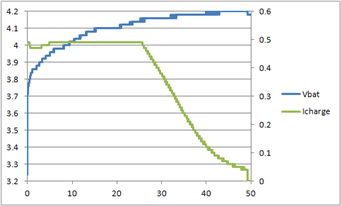
The first period (until ~26 minutes), the battery is charged in Constant Current mode, during which time, the charging current is fixed to 500mA. Early on in the charge cycle, the charger may throttle back the charging current to avoid over heating. In the chart (to the left) there is a slight drop in charging current as a result of rising temperature (the difference between the input and the battery voltages, times the charging current is the source of this heat). This usually only happens when the battery is deeply discharged.
Once the battery voltage reaches 4.2V, the charger transitions to Constant voltage and the charging current is controlled to keep the battery voltage as 4.2V. In the chart at the left it appears that the switch over to Constant voltage occurs at 4.15V, but his is mostly likely due to current induced shifting of the microcontrollers ground reference relative to the charger and battery (something I should investigate later). Charging continues until the charging current required to keep the battery voltage at 4.2V drops to < 25 mA.
Another look at the charging waveforms shows the accumulated charge in the battery as the charging process continues. The green signal shows the accumulated charge over time. At the switch over point to Constant Voltage ~50% of the total charge time), the battery has received ~70% of its total charge. In the remaining time, the battery charging process is slowing down as we slowly bring the cell to full charge.

It was during one of my many charge and discharge cycles that I began to notice that my batter was charging much faster than expected. I also noticed that the same was true for the discharge cycle times. I began to start computing total charge and discharge metrics and then verified that the batteries that I were using were falling far short of their rated capacities (measured between 220mAh and 290mAh for a rated 1200mAh cell). Not exactly the performance that I was hoping for, but not the end of the world either. I will limp by with these cells until some new one arrive.
Boost mode - In boost mode, the microcontroller enables the boost if there is sufficient battery voltage (currently 2.7V), or else prepares the device for shutdown. With the boost running at 5V, I also sub regulate the microcontrollers voltage to 3.3V. The boost regulator has shown itself to perform well across the voltage range of the battery (4.2 to 2.7V) with only the slightest drop off while delivery 500mA (the output dropped to 4.86V with the battery at 2.7V). The boost mode can be terminated by pressing and holding the pushbutton for > 2 seconds. The pushbutton is also used to change the mode (shown by the LEDs) during boost mode. This is a feature is intended for future uses (related to the robot operations), but was useful for changing debug modes during troubleshooting.
Here is a picture of 'Walky' with the new power pack (rev 2 - only a single rework jumper) installed:
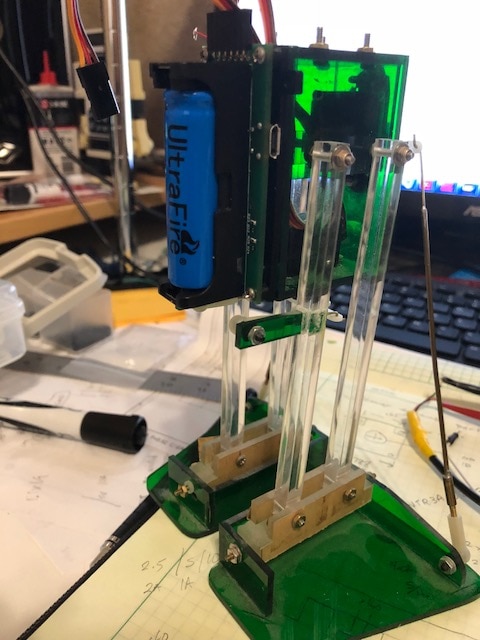
In order to properly mount the power pack to 'Walky' I needed to create a plate to allow the mounting screws to fit within the 'boxy' body of the robot. It was another great reason to fire up the 3-D printer and whip up a little board.
The mounting plate screws direct to the back wall of the body and offers standoffs to allow room for the back mounted components and the micro USB connector. The mounting plate also has some 'ears' to allow mounting of the rear facing sensors (to be added later). With the power pack mounted, 'Walky' tips nicely to side as the feet are pivoted back and forth, allowing 'Walky' to raise the opposite foot, while the lifted leg is driven forward. So far, so good.
I may need to re-visit this assembly later if it becomes necessary to swap the battery holder to accommodate the new 'buttonless' battery (swap from a polarity protected battery holder to a non-protected model). Oh well, there is always room to improve.
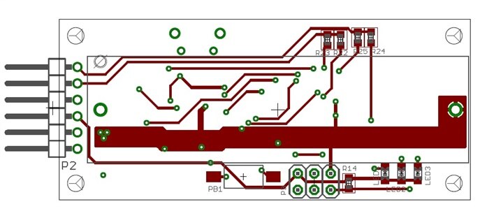
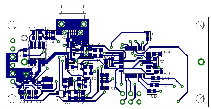
Here are the schematic and layout of the power pack assembly:

The grayed out areas are where I removed the hall-effect current sensor and jumpered over the pins associated with the low impedance sense path.
The battery charger is an MCP73831.
The Boost regulator is an PAM2401.
The 3.3V regulator is an AP2127K-3.3
Microcontroller is an ATmega328PB.
The firmware presently is more of a debug version, or work-in-progress. I will post this as I get more of the functionality in place with less of the debug code getting in the way.
Thanks for reading along.
Gene
Top Comments
-

DAB
-
Cancel
-
Vote Up
+5
Vote Down
-
-
Sign in to reply
-
More
-
Cancel
Comment-

DAB
-
Cancel
-
Vote Up
+5
Vote Down
-
-
Sign in to reply
-
More
-
Cancel
Children