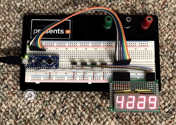
For this project, I wanted to drive a 7-segment display directly with the Arduino Nano Every with a few goals in mind:
- Capable of driving displays with variable number of digits
- Compatible with any led-display architecture: CC (Common Cathode) and CA (Common Anode)
- Reusable/Portable: can be used along with other sketches without affecting their normal operation
- Use the Arduino Nano Every with very basic components (no shift registers or dedicated display-drivers)
- Keep it simple: the same principle can be used for alpha-numeric displays but this may leave fewer GPIO available for other purposes.
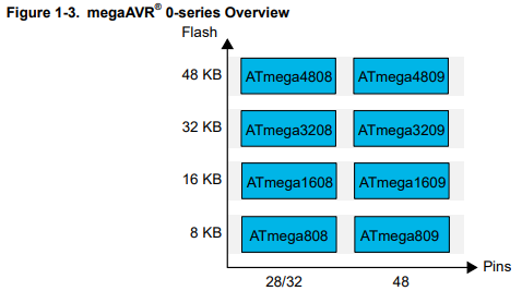
For this particular project I will be using the Arduino IDE and will be operating the registers directly with Bitwise operations. When I decided to work with the new Arduino Nano (with the ATmega4809 micro-controller) this proposed a challenge and a learning experience at the same time since this new processor uses a different set of registers than the old Arduinos (which I'm more familiar with).
Hardware Setup
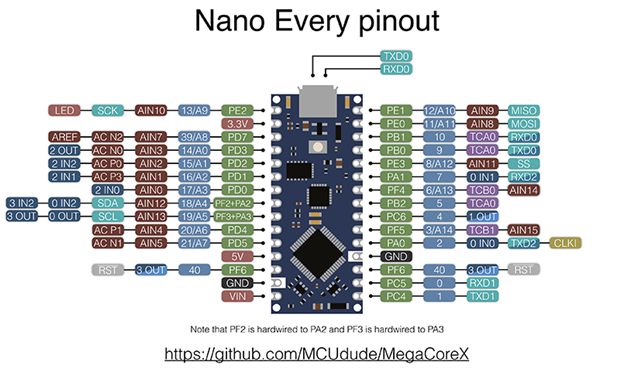
Arduino Nano Every Pinout
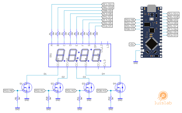
Common Cathode Schematic
CC - BOM
- Arduino Nano EveryArduino Nano Every
- DS1: Common Cathode display. TDCG1060mTDCG1060m
- R1, R2, R3, R4, R5, R6, R7, R8: 220 ohm resistors
- R9, R10, R11, R12: 10k ohm resistors
- Q1, Q1, Q2, Q4: Any N-Channel Signal Mosfet like the BSS138BSS138
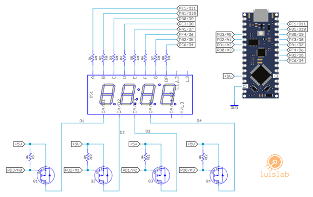
Common Anode Schematic
CA - BOM
- Arduino Nano EveryArduino Nano Every
- DS1: Common Anode display. LDQ-M3604RILDQ-M3604RI
- R1, R2, R3, R4, R5, R6, R7, R8: 220 ohm resistors
- R9, R10, R11, R12: 10k ohm resistors
- Q1, Q1, Q2, Q4: Any P-Channel Signal Mosfet like the NTR1P02NTR1P02
Source code overview
I want to expand on the key aspects of the code. One of the reasons I decided to write directly to the port registers is because I wanted to use this source code along with other projects. To make this process simpler, I will be using masks in order to change the GPIO in use by the display only.
Setup
The most important part of the code initialization comes in the form of two arrays:
- segmentChar: defines how each segment of the display is switchen On/Off to display each digit
- dirMask: defines which digital pins will be used as outputs for each segment.
// Common Cathode  Segment GFEDCBA
byte segmentChar[10]  = {B00111111, // 0
                         B00000110, // 1
                         B01011011, // 2
                         B01001111, // 3
                         B01100110, // 4
                         B01101101, // 5
                         B01111101, // 6
                         B00000111, // 7
                         B01111111, // 8
                         B01101111, // 9
                        };

      /*   |-- A-PE0 --|
       *   |           |
       *  F| PF4   PB1 |B
       *   |           |
       *   |-- G-PB2 --|
       *   |           |
       *  E| PA1   PB0 |C
       *   |           |
       *   |-- D-PE3 --| o PC6
      */
byte dirMask[5] = {B00000010, // PORTA ATmega4809
                   B00000111, // PORTB ATmega4809
                   B01000000, // PORTC ATmega4809
                   B00001001, // PORTE ATmega4809
                   B00010000  // PORTF ATmega4809
                  };
Each time a CA (Common Anode) display needs to be operated, the segmentChar array will be inverted with a simple operation.
Working with CC (Common Cathode) and CA (Common Anode) displays
Unfortunately, there isn't a simple Bitwise operation that can fit "universally" both types of displays. To work around this problem, there are simple operations using the masks previously defined, like the following example:
void clearDigit() {                   // Turns off all segments
  if ( this->displayType == 'A' ) {   // Common Anode
    VPORTA.OUT |= this->dirMask[0];
    VPORTB.OUT |= this->dirMask[1];
    VPORTC.OUT |= this->dirMask[2];
    VPORTE.OUT |= this->dirMask[3];
    VPORTF.OUT |= this->dirMask[4];
  } else {                             // Common Cathode
    VPORTA.OUT &= ~this->dirMask[0];
    VPORTB.OUT &= ~this->dirMask[1];
    VPORTC.OUT &= ~this->dirMask[2];
    VPORTE.OUT &= ~this->dirMask[3];
    VPORTF.OUT &= ~this->dirMask[4];
  }
}
Applying Persistence of Vision (PoV)
Since the 7-segment-displays with more than one digit share a Common terminal, we will need to apply PoV to correctly display anything accurately: alternating every digit for a period of time, long enough to be visible to the eye, but short enough to cover all digits without any ghosting or flickering effect.
To correctly apply PoV to the problem we need to do the following:
- Every time there is a change in the number being displayed, the display is turned OFF and the refresh loop should start over from the least significant digit.
- A bitwise rotation (also known as circular shift) to refresh one digit at a time (starting from the least to the most significant digit), leaving the outputs unused by the display OFF or untouched.
void refresh(uint16_t newNumber) {
  if (newNumber != this->currentNumber) {        // Forces refresh from the first digit when there is a new number to display
    this->currentNumber = newNumber;
    // clear display
    // Split the new number into individual digits and calculate the new number of digits
  }
  //display digit
  //Bitwise circular shift to the left
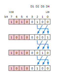
Bitwise circular shift
Let's assume the following scenario:
A 3-digit number needs to be displayed in a 4-digit display, in which case we would like to apply PoV only to 3 digits. For this, a Circular shift operation is needed to turn ON one digit at a time, but this circular shift should apply to 3 bits only. Also, this bitwise-rotation should be a left-shift since it needs to start with the least significant Digit first, all illustrated below:
Such operations are perhaps the most complex but critical part of the code, and can be summarized in these two instructions:
// digitCount holds the the number of digits to be displayed
digitShiftMask = 0xFF >> (8 - digitCount);

// Bitwise rotation
VPORTD.OUT = (VPORTD.OUT & ~digitShiftMask) | (digitShiftMask & ((VPORTD.OUT << 1) | ((VPORTD.OUT & digitShiftMask) >> (digitCount - 1))));
Improving the Persistence of Vision (PoV)
To complete this project, there is one last change needed -Adjusting the refresh rate of each digit-. This is a very important step, but first let me illustrate what is happening with the code as is when we try to display the number "1234" without any change.
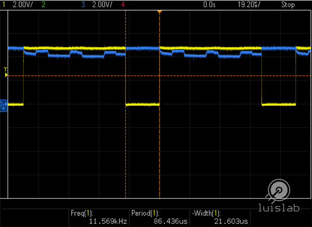
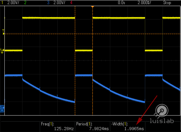
As you can see in the picture above, each digit is displayed for a very short period of time, so short it doesn't provide the Mosfets enough time to switch state (on-off). Each digit displayed looks like it's mixed with the next digit refreshed (ghosting), so our "1234" example turns like these digits are merged together "1+4, 2+1, 3+2, 4+3".
Yellow: Mosfet - Gate (Digit1, Arduino Pin A0), Blue: Mosfet - Drain (Common Anode - Digit1 of the display)
To solve the problem, each digit needs to be displayed for a very short time but long enough that it will provide each Mosfet time to switch to OFF state. Such time should not be long or it may negatively affect the display adding flickering. To make this project more useful for many different uses I wanted to add a mechanism to accurately refresh the display without affecting other pieces of code. Naturally the best way to achieve this without using millis() or micros() in the Arduino is to use timers.
Timers in the new Arduinos with the ATmega4809 micro-controller are a little different to handle in the code than their older siblings (different set of registers), of course, there are other ways to do this but I just implemented the easiest I could come by without changing a lot of code and without changing the default Prescaler value which may negatively affect the behavior of time dependent Arduino functions like PWM, the Servo library, and functions like delay(), micros(), millis(), etc.
Timer/Counter type B (TCB)
The megaAVR 0-series of micro-controllers are equipped with powerful timers that cover a wide area of applications. The Timer/Counter Type B (TCB) offers a variety of features, operation modes and flexibility to perform the very basic functions of a simple timer.
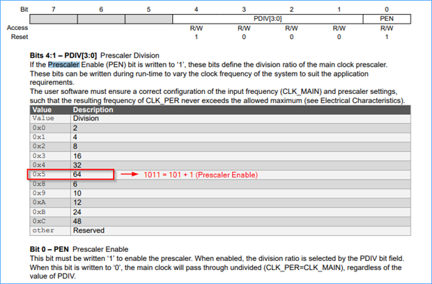
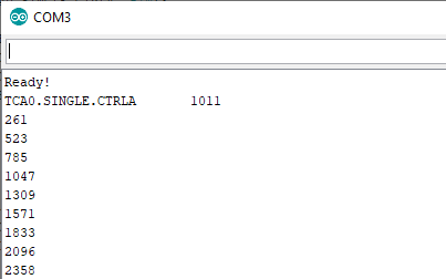
First, I want to find out what the default Prescaler division is and the overflow information, for which I wrote a simple program to verify such information:
void setup() {
  Serial.begin(9600); // start serial for output
  while (!Serial);    // If the Leonardo or Micro is used, wait for the serial monitor to open.
  Serial.println("Ready!");

  Serial.print("TCA0.SINGLE.CTRLA\t");
  Serial.println(TCA0.SINGLE.CTRLA, BIN);


  TCB0.CCMP = 0xFFFF;                                // Value to compare with. Highest value
  TCB0.CTRLA = TCB_CLKSEL_CLKTCA_gc | TCB_ENABLE_bm; // Use Timer/Counter type A (TCA), enable timer
  TCB0.CTRLB = TCB_CNTMODE_INT_gc;                   // Use timer compare mode
  TCB0.INTCTRL = TCB_CAPT_bm;                        // Enable the interrupt
}


void loop() {
}


ISR(TCB0_INT_vect) {
  TCB0.INTFLAGS = TCB_CAPT_bm; // Clear the interrupt flag
  Serial.println(millis());
}
According to output, the default Prescaler division is 64 when using the TCA clock.
Period calculation
The 16-bit timer overflow calculation, which pretty much matches the Serial output (milliseconds)
With those calculations in mind, I found that 2ms is enough time to display each digit providing good Persistence of Vision (POV) and providing each Mosfet enough time to switch state:
With 2ms and our current setup, the overflow value of 500 (0x01F4) will require the following changes to the code
// Timer Setup
TCB0.CCMP = 0x01F4; // Value to compare with (500 cycles). 2ms

ISR(TCB0_INT_vect) {
  LedDisplay.refresh(rpm);
  TCB0.INTFLAGS = TCB_CAPT_bm;
}
Yellow: Mosfet - Gate (Digit1, Arduino Pin A0), Blue: Mosfet - Drain (Common Anode - Digit1 of the display)
As an added bonus, there is no flickering in the project demo video which lead us to conclude that we are achieving a nice refresh rate.
Final source code
With all the challenges this project represented, I wrote a complete piece of code which can handle any type of display (CC - Common Cathode and CA - Common Anode) and can be reused pretty much with any project. This particular example will display a number (starting with zero) and will increment it by one every quarter of a second (250ms).
Note that this 250ms interval is calculated with the delay() function demonstrating that the display is refreshed normally and works with other pieces of code.
//Code for the Arduino Uno
/*
          |--A--|   |-----| L1|-----| o |-----|
          |F   B|   |     | o |     | L3|     |
          |--G--|   |-----| L2|-----|   |-----|
          |E   C|   |     | o |     |   |     |
          |--D--|oDP|-----|o  |-----|o  |-----|
             D1        D2        D3       D4
*/


#define DISPLAY_DIGITS 4 // Number of digits of 7-Segment display


class Led7SegmentDisplay {
  private:
    // Common Cathode  Segment GFEDCBA
    byte segmentChar[10]  = {B00111111, // 0
                             B00000110, // 1
                             B01011011, // 2
                             B01001111, // 3
                             B01100110, // 4
                             B01101101, // 5
                             B01111101, // 6
                             B00000111, // 7
                             B01111111, // 8
                             B01101111, // 9
                            };


    byte dirMask[5] = {B00000010, // PORTA ATmega4809
                       B00000111, // PORTB ATmega4809
                       B01000000, // PORTC ATmega4809
                       B00001001, // PORTE ATmega4809
                       B00010000  // PORTF ATmega4809
                      };


    uint8_t displayDigits; // Number of Digits of the Display
    uint8_t digitCount;    // Number of digits of the Number being/to be displayed
    uint8_t digitIndex;    // Controls the Digit that is being refreshed at the moment
    char    displayType;   // Display type: a,A (Common Anode), else (Common Cathode)
    byte    dispTypeMask;  // Mask according to the number of digits of the display


    uint8_t digitShiftMask;


    uint16_t currentNumber; // Current number displayed


    uint8_t split[5] = {0, 0, 0, 0, 0}; // to Split the number into individual digits


  public:
    /* function Led7SegmentDisplay
     *   digits    : display digits
     *   common_pin: 'a', 'A' Common Anode, else common cathode
     */


    Led7SegmentDisplay(uint8_t digits, char display_type) {
      this->displayDigits   = digits;


      this->currentNumber  = pow(10, this->displayDigits);


      this->digitCount = 0;
      this->digitIndex  = 0;
      this->displayType = toupper(display_type);


      this->dispTypeMask = 0xFF >> (8 - this->displayDigits);


      init();
    }


    void init() {
      VPORTA.DIR |= this->dirMask[0]; // sets ATmega4809 digital pins as outputs (Segment E)
      VPORTB.DIR |= this->dirMask[1]; // sets ATmega4809 digital pins as outputs (Segment G, B, C)
      VPORTC.DIR |= this->dirMask[2]; // sets ATmega4809 digital pins as outputs (Segment DP - Decimal Point)
      VPORTE.DIR |= this->dirMask[3]; // sets ATmega4809 digital pins as outputs (Segment D, A)
      VPORTF.DIR |= this->dirMask[4]; // sets ATmega4809 digital pins as outputs (Segment F)


      VPORTD.DIR |= this->dispTypeMask; //sets ATmega analog pins A# as Outputs // Digit D1 .. Dn (Dn = A0)
    }


    void clearDigit() {                   // Turns off all segments
      if ( this->displayType == 'A' ) {   // Common Anode
        VPORTA.OUT |= this->dirMask[0];
        VPORTB.OUT |= this->dirMask[1];
        VPORTC.OUT |= this->dirMask[2];
        VPORTE.OUT |= this->dirMask[3];
        VPORTF.OUT |= this->dirMask[4];
      } else {                             // Common Cathode
        VPORTA.OUT &= ~this->dirMask[0];
        VPORTB.OUT &= ~this->dirMask[1];
        VPORTC.OUT &= ~this->dirMask[2];
        VPORTE.OUT &= ~this->dirMask[3];
        VPORTF.OUT &= ~this->dirMask[4];
      }
    }


    void refresh(uint16_t newNumber) {
      if (newNumber != this->currentNumber) {        // Forces refresh from the first digit when there is a new number to display
        this->currentNumber = newNumber;
        digitCount = 0;
        while (newNumber > 0 || digitCount == 0) {   // Split the new number into individual digits and calculate the new number of digits//
          split[digitCount++] = newNumber % 10;
          newNumber     /= 10;
        }
        digitIndex = 0;


        clearDigit();
        if ( this->displayType == 'A' )
          VPORTD.OUT = (VPORTD.OUT | this->dispTypeMask) & (0xFF ^ (0x01 << (digitCount - 1)));
        else
          VPORTD.OUT = (VPORTD.OUT & ~this->dispTypeMask) | (0x01 << (digitCount - 1));
        digitShiftMask = 0xFF >> (8 - digitCount);
      }


      /*    |-- A-PE0 --|
       *    |           |
       *   F| PF4   PB1 |B
       *    |           |
       *    |-- G-PB2 --|
       *    |           |
       *   E| PA1   PB0 |C
       *    |           |
       *    |-- D-PE3 --| o PC6
      */


      clearDigit(); //turns off digit


      byte character = segmentChar[split[digitIndex]];
      if ( this->displayType == 'A' ) {
        VPORTA.OUT = (VPORTA.OUT | dirMask[0]) ^ (bitRead(character, 4) << 1);
        VPORTB.OUT = (VPORTB.OUT | dirMask[1]) ^ (bitRead(character, 6) << 2 | bitRead(character, 1) << 1 | bitRead(character, 2) << 0);
        VPORTE.OUT = (VPORTE.OUT | dirMask[3]) ^ (bitRead(character, 0) << 0 | bitRead(character, 3) << 3);
        VPORTF.OUT = (VPORTF.OUT | dirMask[4]) ^ (bitRead(character, 5) << 4);
      } else {
        VPORTA.OUT = (VPORTA.OUT & ~dirMask[0]) ^ (bitRead(character, 4) << 1);
        VPORTB.OUT = (VPORTB.OUT & ~dirMask[1]) ^ (bitRead(character, 6) << 2 | bitRead(character, 1) << 1 | bitRead(character, 2) << 0);
        VPORTE.OUT = (VPORTE.OUT & ~dirMask[3]) ^ (bitRead(character, 0) << 0 | bitRead(character, 3) << 3);
        VPORTF.OUT = (VPORTF.OUT & ~dirMask[4]) ^ (bitRead(character, 5) << 4);
      }


      // Bitwise rotation to the left (just for the number of bits equivalent to the number)
      VPORTD.OUT = (VPORTD.OUT & ~digitShiftMask) | (digitShiftMask & ((VPORTD.OUT << 1) | ((VPORTD.OUT & digitShiftMask) >> (digitCount - 1))));
      digitIndex = ++digitIndex % digitCount;
    };
};


//Led7SegmentDisplay LedDisplay(4, 'C'); // Common Cathode
Led7SegmentDisplay LedDisplay(4, 'A'); // Common Anode


uint16_t      rpm = 0;


void setup() {
  TCB0.CCMP = 0x01F4;                                // Value to compare with (500). 2ms
  TCB0.CTRLA = TCB_CLKSEL_CLKTCA_gc | TCB_ENABLE_bm; // Use Timer/Counter type A (TCA), enable timer
  TCB0.CTRLB = TCB_CNTMODE_INT_gc;                   // Use timer compare mode
  TCB0.INTCTRL = TCB_CAPT_bm;                        // Enable the interrupt
}


void loop() {
  rpm++;
  delay(250);
}


ISR(TCB0_INT_vect) {
   LedDisplay.refresh(rpm);
   TCB0.INTFLAGS = TCB_CAPT_bm; // Clear the interrupt flag
}
Technical details:
- Digit display time: 2ms
- Display refresh rate: approx. 500Hz / digits_displayed. e.g: 2 digits = 1 / (2digits x 2ms) = 250Hz
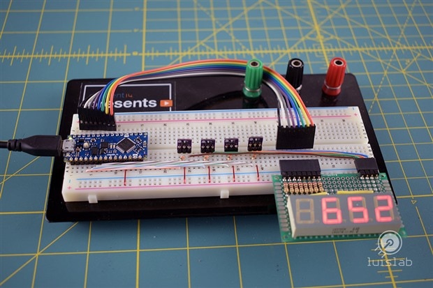
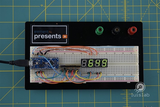
| {gallery:width=648,height=432,autoplay=false} 7-segment display demo |
|---|
Common Anode demo: 7-segment display |
Common Cathode demo: 7-segment display |
Thanks for reading and a big thanks to Element14 for sponsoring my project!
Luis






Top Comments
-

three-phase
-
Cancel
-
Vote Up
+2
Vote Down
-
-
Sign in to reply
-
More
-
Cancel
-

luislabmo
in reply to three-phase
-
Cancel
-
Vote Up
+1
Vote Down
-
-
Sign in to reply
-
More
-
Cancel
Comment-

luislabmo
in reply to three-phase
-
Cancel
-
Vote Up
+1
Vote Down
-
-
Sign in to reply
-
More
-
Cancel
Children