element14 Community
element14 Community
    Register Log In
  • Site
  • Search
  • Log In Register
  • About Us
  • Community Hub
    Community Hub
    • What's New on element14
    • Feedback and Support
    • Benefits of Membership
    • Personal Blogs
    • Members Area
    • Achievement Levels
  • Learn
    Learn
    • Ask an Expert
    • eBooks
    • element14 presents
    • Learning Center
    • Tech Spotlight
    • STEM Academy
    • Webinars, Training and Events
    • Learning Groups
  • Technologies
    Technologies
    • 3D Printing
    • FPGA
    • Industrial Automation
    • Internet of Things
    • Power & Energy
    • Sensors
    • Technology Groups
  • Challenges & Projects
    Challenges & Projects
    • Design Challenges
    • element14 presents Projects
    • Project14
    • Arduino Projects
    • Raspberry Pi Projects
    • Project Groups
  • Products
    Products
    • Arduino
    • Avnet Boards Community
    • Dev Tools
    • Manufacturers
    • Multicomp Pro
    • Product Groups
    • Raspberry Pi
    • RoadTests & Reviews
  • Store
    Store
    • Visit Your Store
    • Choose another store...
      • Europe
      •  Austria (German)
      •  Belgium (Dutch, French)
      •  Bulgaria (Bulgarian)
      •  Czech Republic (Czech)
      •  Denmark (Danish)
      •  Estonia (Estonian)
      •  Finland (Finnish)
      •  France (French)
      •  Germany (German)
      •  Hungary (Hungarian)
      •  Ireland
      •  Israel
      •  Italy (Italian)
      •  Latvia (Latvian)
      •  
      •  Lithuania (Lithuanian)
      •  Netherlands (Dutch)
      •  Norway (Norwegian)
      •  Poland (Polish)
      •  Portugal (Portuguese)
      •  Romania (Romanian)
      •  Russia (Russian)
      •  Slovakia (Slovak)
      •  Slovenia (Slovenian)
      •  Spain (Spanish)
      •  Sweden (Swedish)
      •  Switzerland(German, French)
      •  Turkey (Turkish)
      •  United Kingdom
      • Asia Pacific
      •  Australia
      •  China
      •  Hong Kong
      •  India
      •  Korea (Korean)
      •  Malaysia
      •  New Zealand
      •  Philippines
      •  Singapore
      •  Taiwan
      •  Thailand (Thai)
      • Americas
      •  Brazil (Portuguese)
      •  Canada
      •  Mexico (Spanish)
      •  United States
      Can't find the country/region you're looking for? Visit our export site or find a local distributor.
  • Translate
  • Profile
  • Settings
Op-Amp-a-Palooza
  • Challenges & Projects
  • Project14
  • Op-Amp-a-Palooza
  • More
  • Cancel
Op-Amp-a-Palooza
Blog Adding additional capabilities to my KORG volca modular synthesizer and learning about Op-Amps at the same time. Part 2 - Power supply bring up and Analyzing the Noise Source.
  • Blog
  • Forum
  • Documents
  • Events
  • Polls
  • Files
  • Members
  • Mentions
  • Sub-Groups
  • Tags
  • More
  • Cancel
  • New
Join Op-Amp-a-Palooza to participate - click to join for free!
  • Share
  • More
  • Cancel
Group Actions
  • Group RSS
  • More
  • Cancel
Engagement
  • Author Author: genebren
  • Date Created: 18 Apr 2022 8:26 PM Date Created
  • Views 17414 views
  • Likes 11 likes
  • Comments 2 comments
  • opampsch
  • Op-amp-a-Palooza
Related
Recommended

Adding additional capabilities to my KORG volca modular synthesizer and learning about Op-Amps at the same time. Part 2 - Power supply bring up and Analyzing the Noise Source.

genebren
genebren
18 Apr 2022

In my prior Op-Amp-a-Palooza post (/challenges-projects/project14/opampapalooza/b/blog/posts/adding-additional-capabilities-to-my-korg-volca-modular-synthesizer-and-learning-about-op-amps-at-the-same-time) I described, at a high level, my design and the intent of my project.  As a status report, I am still awaiting a few parts that I need to complete my build.  So far, I have build up the power supplies, main processor, USB transceiver and the noise co-processor circuits.  Everything has test OK up to this point, so I decided to work on the firmware for the noise generator circuit.

image

Here is the partially completed board.  The two longer wires are test points for testing the noise source (left is to measure the weighted sum waveform and right is to control the number of bits used, which is connected to a power supply). In between the two test points is a jumper added to the EEPROM chip to fix the write protect (should have been pulled low to allow write to the EEPROM).

Power Supply Bring Up.

As a part of the power supply section of the board, there is the first Op-amp of this design.  In this case, the Op-amp is configured as a simple voltage follower, with the input attenuated to 50% of the voltage rail (in this case 3.3V).  Here is the circuit:

image

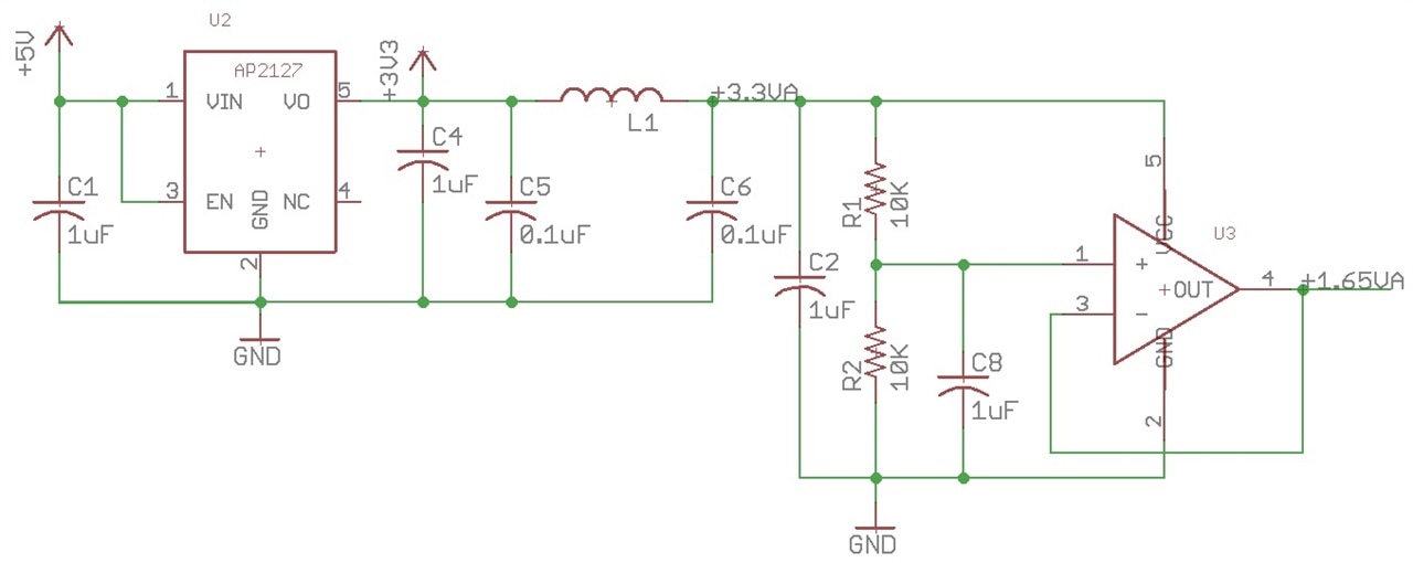
The output of the circuit was measured at 1.65V, with very little noise.  This circuit will be used to mid-point bias some of the other Op-amps in the design.  When I initially designed this board, I had decided to use an STMicroelectronics - LMV321ILT Op-Amp. When element14 offered up a sample of Op-Amps, I decided to give the Microchip Technology - MCP6V31T-E/OT Op-Amp a try as some of the Op-Amps on the board.  Unfortunately, I misread the specification sheet on this part (I looked at the pinout for the 'U' version of the chip, which matched the LMV321 part, but the part in the kit was not the 'U' version, so all the pins were different).  After removing the  MCP6V31T chip and inserting the LMV321 chip, the circuit worked correctly.

Analyzing the Noise Source.

The noise generator is made up of a ATTINY85 processor, running firmware to act as a Linear Feedback Shift Register (LFSR), using a 39 bit register length to develop a Pseudo Random bit sequence. I had added a few tweaks to this design, attempting to produce as spectrally flat as possible, i.e white noise. To this end, I add a circuit to sum up to four bits of the LFSR pattern, using a binary weighted adder circuit.  The ATTINY processor also includes an analog input that can be used to control the number of bits that will be used in the output waveform.

The LFSR algorithm is executed at a 200KHz rate, meaning that the highest output frequency fundamental component is 100KHz.  As more bits are added to the binary weighted adder, the number of discrete voltage levels are increased (1 bit - 2 levels, 2 bits - 4 levels, 3 bits - 8 levels and with 4 bits - 16 levels), and a result output waveform becomes a bit more complex.

Here are some screen shots of the output waveform and the spectrum at the various active output bits:

image  imageimage

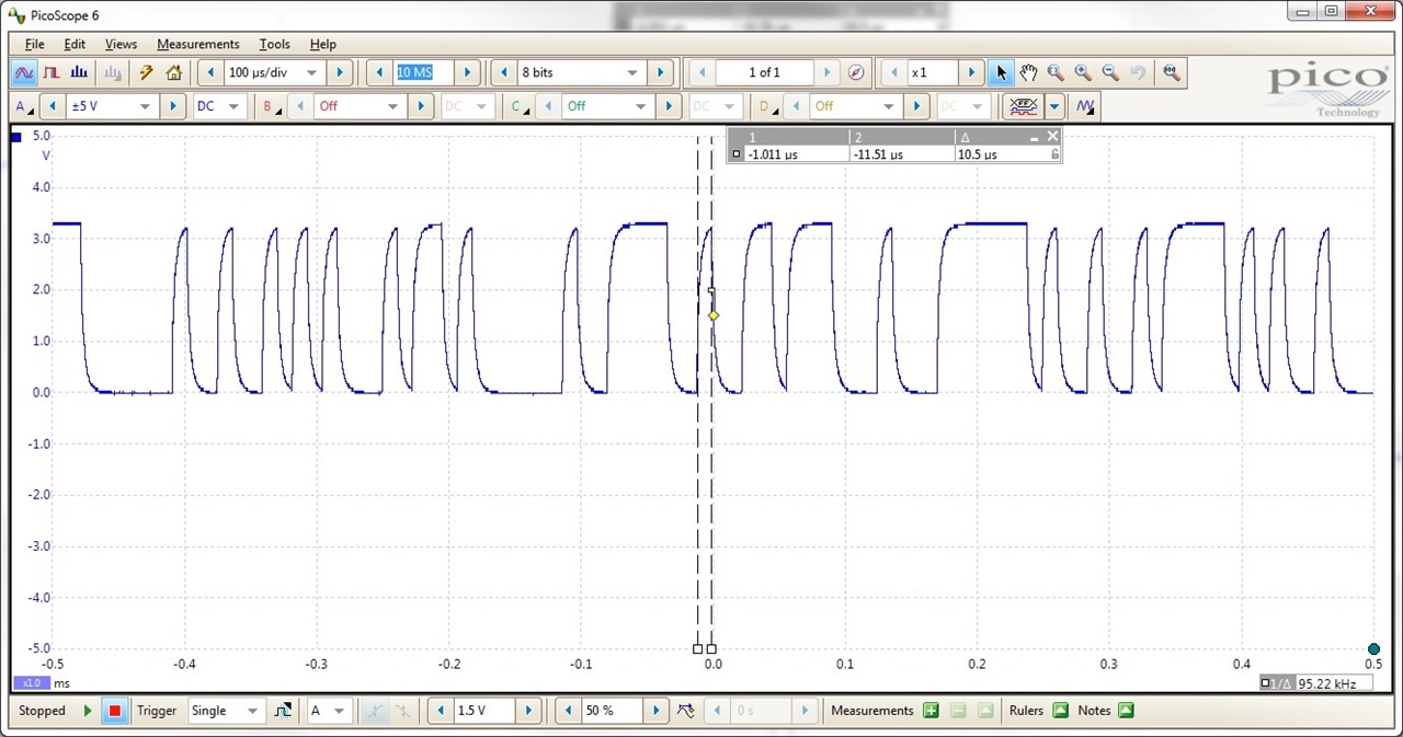
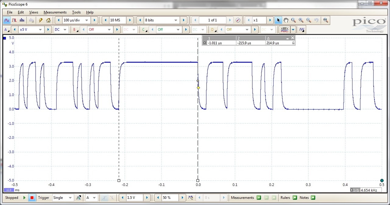
With a single bit active the output waveform is either high or low.  The first image shows the minimal pulse width capture and the second one shows the maximal pulse width (or at least the longest that I was willing to wait for). With this setup, the spectrum is flat to +/-10 dBu up to about 60KHz and pretty flat up to 20KHz.

imageimageimage

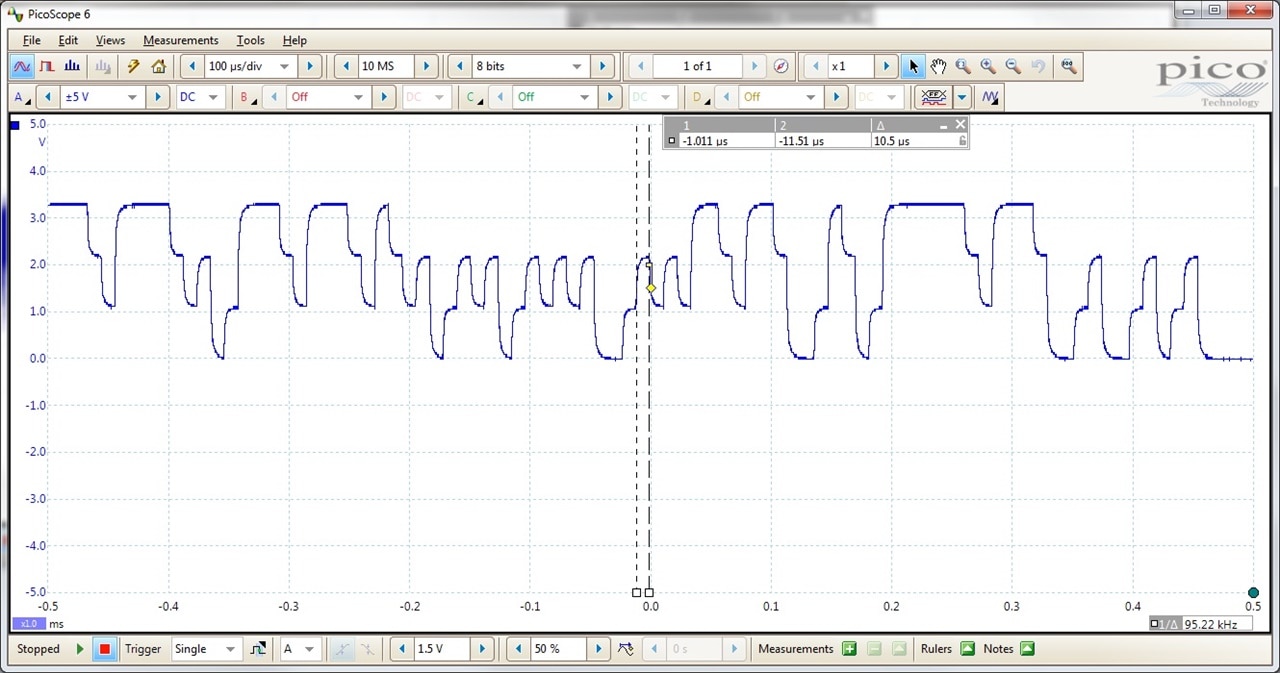
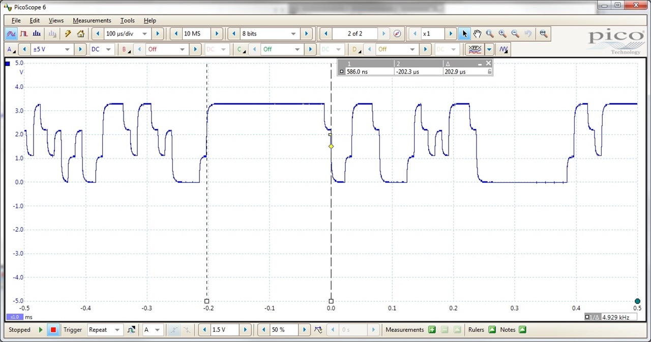
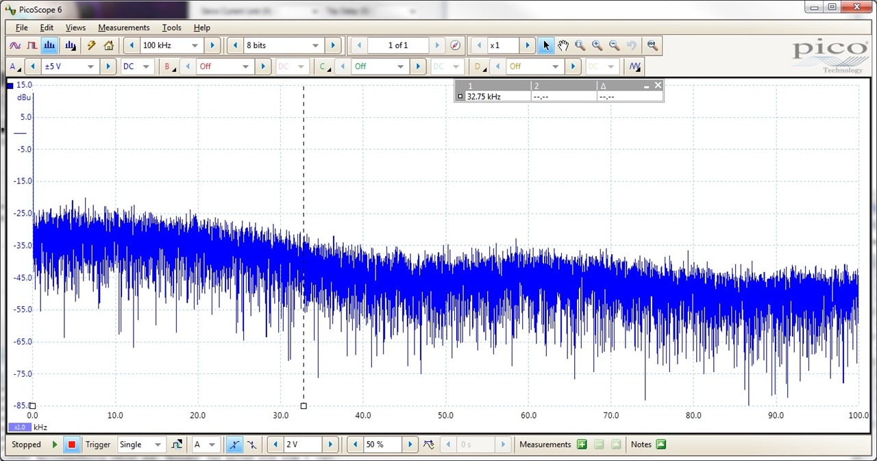
With two bits active the output waveform is one of four levels.  The first image shows the minimal pulse width capture and the second one shows the maximal pulse width. With this setup, the spectrum is flat to +/-10 dBu up to about ~33KHz and pretty flat up to 20KHz (rolling off about 3dBu at 20KHz).

imageimageimage

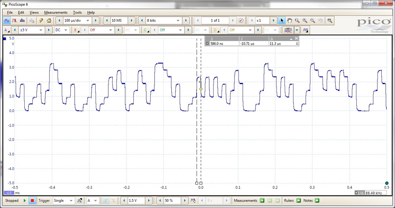
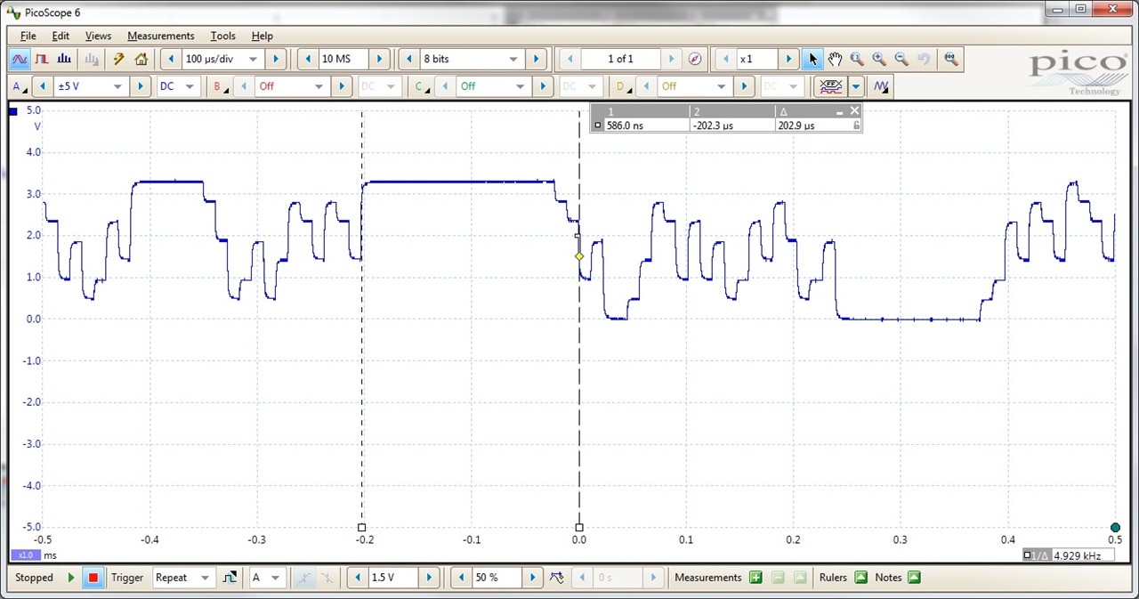
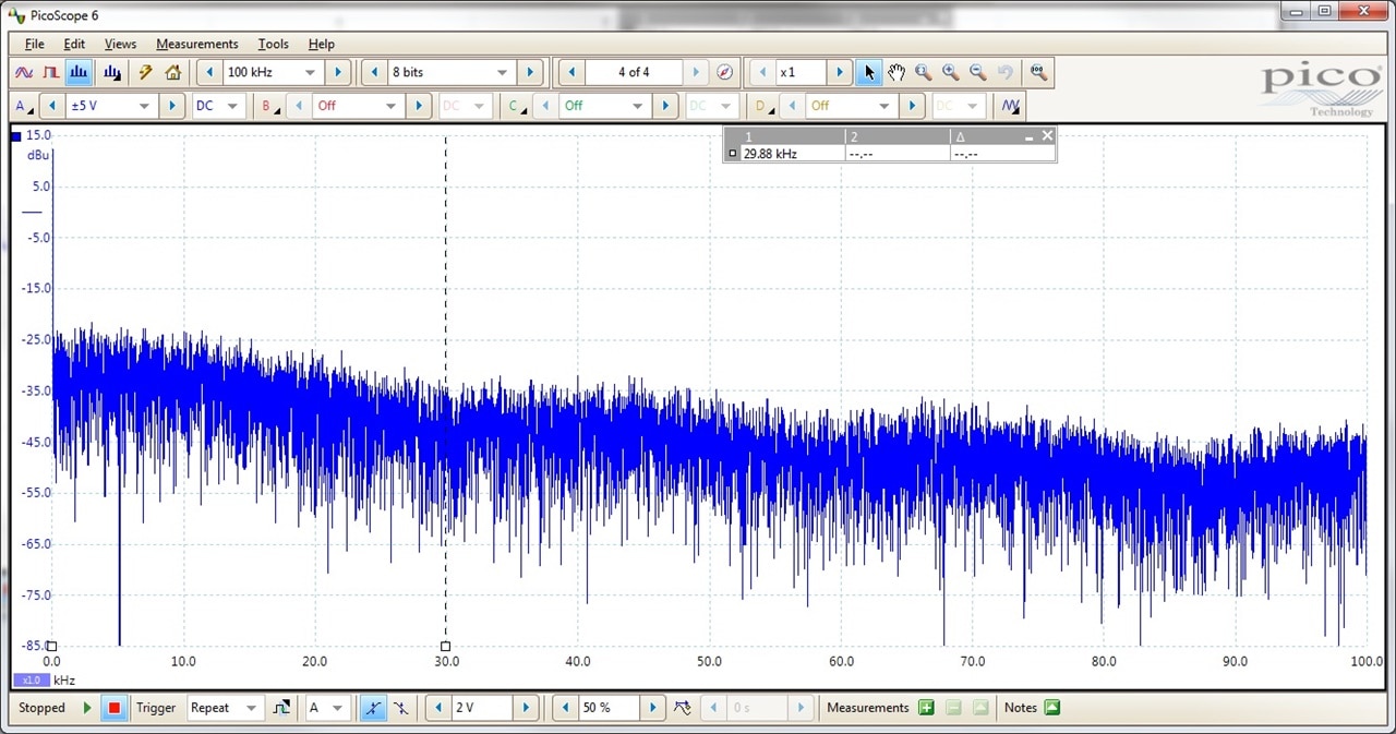
With three bits active the output waveform is one of eight levels.  The first image shows the minimal pulse width capture and the second one shows the maximal pulse width. With this setup, the spectrum is flat to +/-10 dBu up to about ~30KHz and pretty flat up to 20KHz (rolling off about 5dBu at 20KHz).

imageimageimage

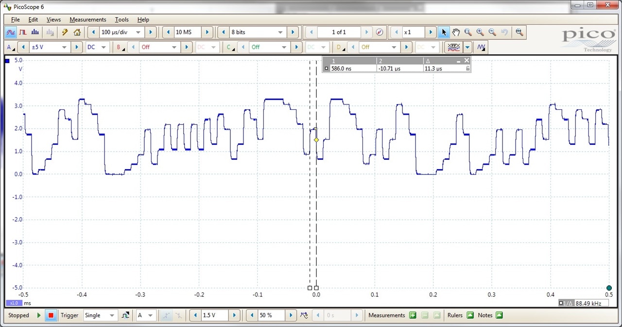
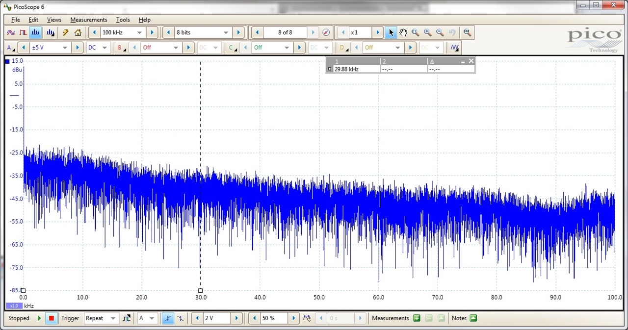
With a four bits active the output waveform is one of sixteen levels.  The first image shows the minimal pulse width capture and the second one shows the maximal pulse width. With this setup, the spectrum is flat to +/-10 dBu up to about ~30KHz and pretty flat up to 20KHz (rolling off about 9dBu at 20KHz).

It will be interesting to hear the differences (if possible) in these four versions of a 'white noise' spectrum, but that will have to wait at bit.  My next step will be to add more components to the board as my parts arrive.

Thanks for reading along.  Keep on the lookout for further updates.

  • Sign in to reply
  • genebren
    genebren over 3 years ago in reply to DAB

    Thanks!  I had tried a bunch of transistors and zener diodes to see if I could have created a reverse biased noise source, but none of the parts I had on hand would quite get into the noise mode at 5V (sure they worked at higher voltages).  I found some great ideas in "The Art of Electronics" book, namely a noise generator chip (MM5437) and a write up on 'Feedback shift register sequences".  This led me to a very usable design, which I could not help but tinker with.

    • Cancel
    • Vote Up 0 Vote Down
    • Sign in to reply
    • More
    • Cancel
  • DAB
    DAB over 3 years ago

    I like your noise generation approach.

    • Cancel
    • Vote Up 0 Vote Down
    • Sign in to reply
    • More
    • Cancel
element14 Community

element14 is the first online community specifically for engineers. Connect with your peers and get expert answers to your questions.

  • Members
  • Learn
  • Technologies
  • Challenges & Projects
  • Products
  • Store
  • About Us
  • Feedback & Support
  • FAQs
  • Terms of Use
  • Privacy Policy
  • Legal and Copyright Notices
  • Sitemap
  • Cookies

An Avnet Company © 2025 Premier Farnell Limited. All Rights Reserved.

Premier Farnell Ltd, registered in England and Wales (no 00876412), registered office: Farnell House, Forge Lane, Leeds LS12 2NE.

ICP 备案号 10220084.

Follow element14

  • X
  • Facebook
  • linkedin
  • YouTube