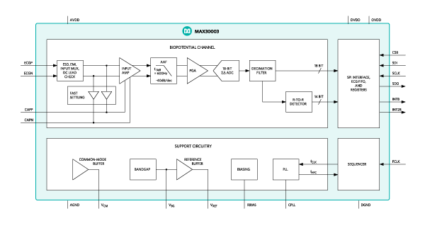
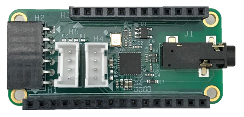
1. I have evaluated MAX30003C AFE with ECG, this chip is used in some Mobile for Heat-rate detection. Use MAX30003WING Evaluation Kit for the MAX30003 Biopotential AFE | Maxim Integrated is easy and quick, just fetch I2C signals. Here is how the ECG monitor works

Two stage Op-amp with internal filter work together.

Here is sample arduino code with arduino library
 #include <TimerOne.h>
#include<SPI.h>
#include "MAX30003.h"

#define MAX30003_CS_PIN   7
#define CLK_PIN          6

volatile char SPI_RX_Buff[5] ;
volatile char *SPI_RX_Buff_Ptr;
int i=0;
unsigned long uintECGraw = 0;
signed long intECGraw=0;
uint8_t DataPacketHeader[20];
uint8_t data_len = 8;
 signed long ecgdata;
 unsigned long data;

char SPI_temp_32b[4];
char SPI_temp_Burst[100];

// 32KHz clock using timer1
void timerIsr()
{
    digitalWrite( CLK_PIN, digitalRead(CLK_PIN ) ^ 1 ); // toggle Digital6 attached to FCLK  of MAX30003
}

void setup()
{
    Serial.begin(115200); //Serial begin

    pinMode(MAX30003_CS_PIN,OUTPUT);
    digitalWrite(MAX30003_CS_PIN,HIGH); //disable device

    SPI.begin();
    SPI.setBitOrder(MSBFIRST);
    SPI.setDataMode(SPI_MODE0);
    SPI.setClockDivider(SPI_CLOCK_DIV4);

    pinMode(CLK_PIN,OUTPUT);

    MAX30003_begin();   // initialize MAX30003

}

void loop()
{
    MAX30003_Reg_Read(ECG_FIFO);

    unsigned long data0 = (unsigned long) (SPI_temp_32b[0]);
    data0 = data0 <<24;
    unsigned long data1 = (unsigned long) (SPI_temp_32b[1]);
    data1 = data1 <<16;
    unsigned long data2 = (unsigned long) (SPI_temp_32b[2]);
    data2 = data2 >>6;
    data2 = data2 & 0x03;

    data = (unsigned long) (data0 | data1 | data2);
    ecgdata = (signed long) (data);

    MAX30003_Reg_Read(RTOR);
    unsigned long RTOR_msb = (unsigned long) (SPI_temp_32b[0]);
   // RTOR_msb = RTOR_msb <<8;
    unsigned char RTOR_lsb = (unsigned char) (SPI_temp_32b[1]);

    unsigned long rtor = (RTOR_msb<<8 | RTOR_lsb);
    rtor = ((rtor >>2) & 0x3fff) ;

    float hr =  60 /((float)rtor*0.008);
   unsigned int HR = (unsigned int)hr;  // type cast to int

    unsigned int RR = (unsigned int)rtor*8 ;  //8ms

     /*Serial.print(RTOR_msb);
     Serial.print(",");
     Serial.print(RTOR_lsb);
     Serial.print(",");
     Serial.print(rtor);
     Serial.print(",");
     Serial.print(rr);
     Serial.print(",");
     Serial.println(hr);      */

      DataPacketHeader[0] = 0x0A;
      DataPacketHeader[1] = 0xFA;
      DataPacketHeader[2] = 0x0C;
      DataPacketHeader[3] = 0;
      DataPacketHeader[4] = 0x02;

      DataPacketHeader[5] = ecgdata;
      DataPacketHeader[6] = ecgdata>>8;
      DataPacketHeader[7] = ecgdata>>16;
      DataPacketHeader[8] = ecgdata>>24;

      DataPacketHeader[9] =  RR ;
      DataPacketHeader[10] = RR >>8;
      DataPacketHeader[11] = 0x00;
      DataPacketHeader[12] = 0x00;

      DataPacketHeader[13] = HR ;
      DataPacketHeader[14] = HR >>8;
      DataPacketHeader[15] = 0x00;
      DataPacketHeader[16] = 0x00;

      DataPacketHeader[17] = 0x00;
      DataPacketHeader[18] = 0x0b;

      for(i=0; i<19; i++) // transmit the data
      {
        Serial.write(DataPacketHeader[i]);

       }

    delay(1);
}

void MAX30003_Reg_Write (unsigned char WRITE_ADDRESS, unsigned long data)
{

  // now combine the register address and the command into one byte:
   byte dataToSend = (WRITE_ADDRESS<<1) | WREG;

   // take the chip select low to select the device:
   digitalWrite(MAX30003_CS_PIN, LOW);

   delay(2);
   SPI.transfer(dataToSend);   //Send register location
   SPI.transfer(data>>16);     //number of register to wr
   SPI.transfer(data>>8);      //number of register to wr
   SPI.transfer(data);      //Send value to record into register
   delay(2);

   // take the chip select high to de-select:
   digitalWrite(MAX30003_CS_PIN, HIGH);
}

void max30003_sw_reset(void)
{
  MAX30003_Reg_Write(SW_RST,0x000000);
  delay(100);
}

void max30003_synch(void)
{
  MAX30003_Reg_Write(SYNCH,0x000000);
}

void MAX30003_Reg_Read(uint8_t Reg_address)
{
   uint8_t SPI_TX_Buff;

   digitalWrite(MAX30003_CS_PIN, LOW);

   SPI_TX_Buff = (Reg_address<<1 ) | RREG;
   SPI.transfer(SPI_TX_Buff); //Send register location

   for ( i = 0; i < 3; i++)
   {
      SPI_temp_32b[i] = SPI.transfer(0xff);
   }

   digitalWrite(MAX30003_CS_PIN, HIGH);
}

void MAX30003_Read_Data(int num_samples)
{
  uint8_t SPI_TX_Buff;

  digitalWrite(MAX30003_CS_PIN, LOW);

  SPI_TX_Buff = (ECG_FIFO_BURST<<1 ) | RREG;
  SPI.transfer(SPI_TX_Buff); //Send register location

  for ( i = 0; i < num_samples*3; ++i)
  {
    SPI_temp_Burst[i] = SPI.transfer(0x00);
  }

  digitalWrite(MAX30003_CS_PIN, HIGH);
}

void MAX30003_begin()
{
    //Start CLK timer
    Timer1.initialize(16);              // set a timer of length 100000 microseconds (or 0.1 sec - or 10Hz => the led will blink 5 times, 5 cycles of on-and-off, per second)
    Timer1.attachInterrupt( timerIsr ); // attach the service routine here

    max30003_sw_reset();
    delay(100);
    MAX30003_Reg_Write(CNFG_GEN, 0x081007);
    delay(100);
    MAX30003_Reg_Write(CNFG_CAL, 0x720000);  // 0x700000
    delay(100);
    MAX30003_Reg_Write(CNFG_EMUX,0x0B0000);
    delay(100);
    MAX30003_Reg_Write(CNFG_ECG, 0x005000);  // d23 - d22 : 10 for 250sps , 00:500 sps
    delay(100);


    MAX30003_Reg_Write(CNFG_RTOR1,0x3fc600);
    max30003_synch();
    delay(100);
}
2. It would be more interesting in customized such function with independent Op-amps, the low power MCP6032 is good for such purpose,
Start Design with simulation tools mindi
Then schematic
Adjust parameters with simulation tools
3. Simply PCB design
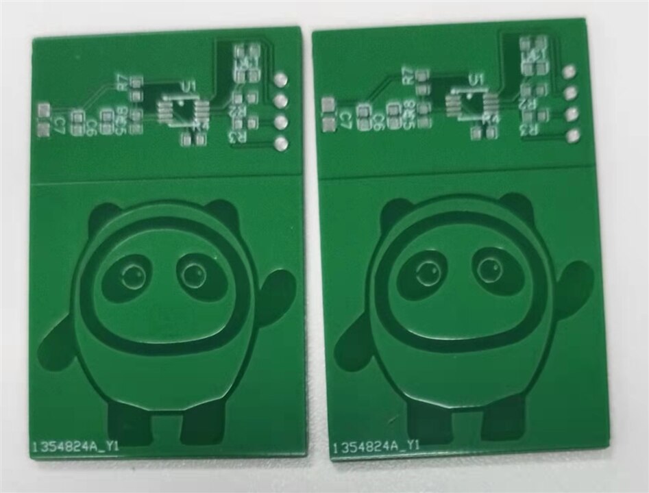
The PCB output with small logo for spare space
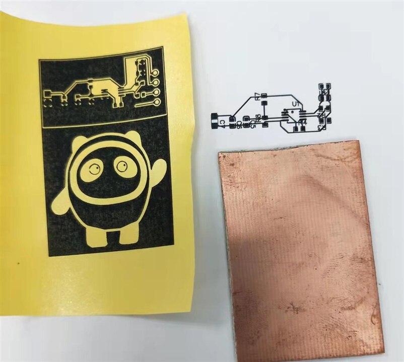
4. The rest is full of difficulties. The sudden disruption in delivery make me difficult to order new parts, I decide to do PCB on my own


Obviously, I fail. The heating plate is not even and no extra thermal transfer paper available. I have to wait for my PCB arrived today from factory.

Next, solder and test the MCP6032 with available resistors . Let me see results.
