element14 Community
element14 Community
    Register Log In
  • Site
  • Search
  • Log In Register
  • About Us
  • Community Hub
    Community Hub
    • What's New on element14
    • Feedback and Support
    • Benefits of Membership
    • Personal Blogs
    • Members Area
    • Achievement Levels
  • Learn
    Learn
    • Ask an Expert
    • eBooks
    • element14 presents
    • Learning Center
    • Tech Spotlight
    • STEM Academy
    • Webinars, Training and Events
    • Learning Groups
  • Technologies
    Technologies
    • 3D Printing
    • FPGA
    • Industrial Automation
    • Internet of Things
    • Power & Energy
    • Sensors
    • Technology Groups
  • Challenges & Projects
    Challenges & Projects
    • Design Challenges
    • element14 presents Projects
    • Project14
    • Arduino Projects
    • Raspberry Pi Projects
    • Project Groups
  • Products
    Products
    • Arduino
    • Avnet Boards Community
    • Dev Tools
    • Manufacturers
    • Multicomp Pro
    • Product Groups
    • Raspberry Pi
    • RoadTests & Reviews
  • Store
    Store
    • Visit Your Store
    • Choose another store...
      • Europe
      •  Austria (German)
      •  Belgium (Dutch, French)
      •  Bulgaria (Bulgarian)
      •  Czech Republic (Czech)
      •  Denmark (Danish)
      •  Estonia (Estonian)
      •  Finland (Finnish)
      •  France (French)
      •  Germany (German)
      •  Hungary (Hungarian)
      •  Ireland
      •  Israel
      •  Italy (Italian)
      •  Latvia (Latvian)
      •  
      •  Lithuania (Lithuanian)
      •  Netherlands (Dutch)
      •  Norway (Norwegian)
      •  Poland (Polish)
      •  Portugal (Portuguese)
      •  Romania (Romanian)
      •  Russia (Russian)
      •  Slovakia (Slovak)
      •  Slovenia (Slovenian)
      •  Spain (Spanish)
      •  Sweden (Swedish)
      •  Switzerland(German, French)
      •  Turkey (Turkish)
      •  United Kingdom
      • Asia Pacific
      •  Australia
      •  China
      •  Hong Kong
      •  India
      •  Korea (Korean)
      •  Malaysia
      •  New Zealand
      •  Philippines
      •  Singapore
      •  Taiwan
      •  Thailand (Thai)
      • Americas
      •  Brazil (Portuguese)
      •  Canada
      •  Mexico (Spanish)
      •  United States
      Can't find the country/region you're looking for? Visit our export site or find a local distributor.
  • Translate
  • Profile
  • Settings
Op-Amp-a-Palooza
  • Challenges & Projects
  • Project14
  • Op-Amp-a-Palooza
  • More
  • Cancel
Op-Amp-a-Palooza
Blog LED Music visualizer - Blog 2: Filter Designs and Simulations
  • Blog
  • Forum
  • Documents
  • Events
  • Polls
  • Files
  • Members
  • Mentions
  • Sub-Groups
  • Tags
  • More
  • Cancel
  • New
Join Op-Amp-a-Palooza to participate - click to join for free!
  • Share
  • More
  • Cancel
Group Actions
  • Group RSS
  • More
  • Cancel
Engagement
  • Author Author: rsjawale24
  • Date Created: 26 Apr 2022 6:07 PM Date Created
  • Views 21718 views
  • Likes 6 likes
  • Comments 5 comments
  • opampsch
  • opamps
  • Op-amp-a-Palooza
  • project14
  • filters
Related
Recommended

LED Music visualizer - Blog 2: Filter Designs and Simulations

rsjawale24
rsjawale24
26 Apr 2022

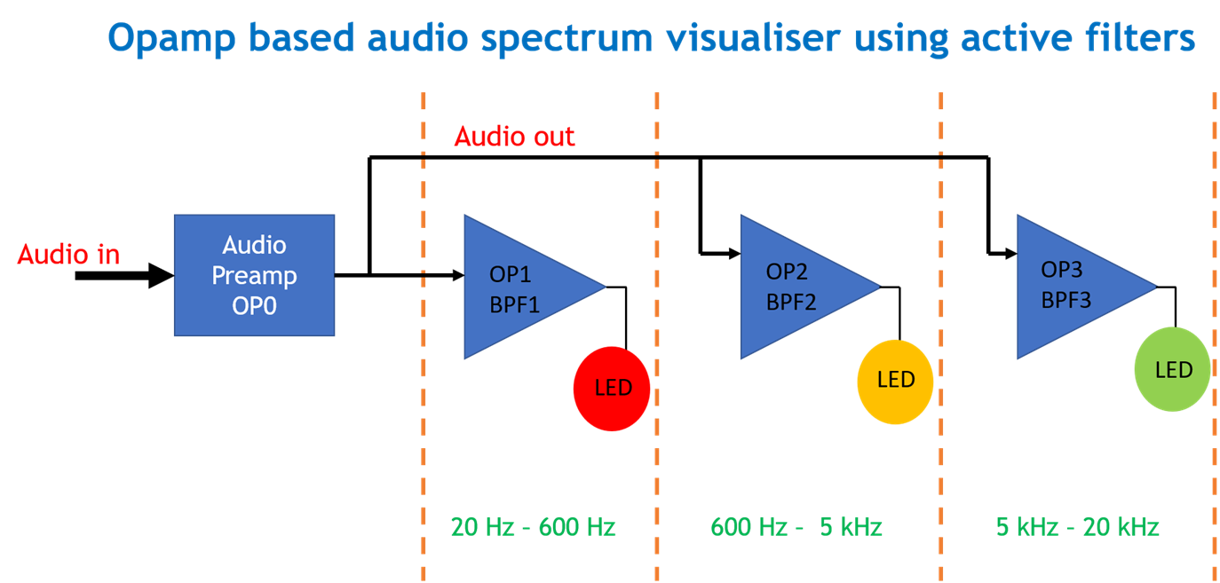
In my last blog (part 1) I introduced the overall idea of the project. The idea was to split the audio spectrum from 20 Hz to 20 kHz using three active filters and each filter's output is connected to LEDs thereby making a LED music visualizer. I also simulated 3 basic filters (LPF,BPF, and HPF) and an active low pass filter to demonstrate the working of active filters.

In this blog, I will do the calculations for the values of the components required to build the active filters and run some simulations before the final hardware build of the circuit. I will be using RC filters with Butterworth response.
image

The first block in the design is the pre-amplifier. A pre-amp is needed as I'm planning to use the audio out of a smartphone which is in the range of few millivolts. This signal needs to be amplified such that it can be fed to the three opamp filters.

The preamp is a very basic non-inverting opamp amplifier with a voltage gain of about 4-5.

Next, step is to decide the bands for the filters.

Audio Bands                   

First, the audio signal (20 Hz - 20 kHz) is split into three bands as follows-

Band Frequency
Band 1 20 Hz - 480 Hz
Band 2 480 Hz - 3 kHz
Band 3 3 kHz - 20 kHz

Since the audio spectrum is limited to 20 Hz - 20 kHz, the first band can be filtered out using a low pass filter with a cutoff freq of 480 Hz, this LPF will allow all the frequencies from 20Hz to 480 Hz and attenuate the frequencies above 480 Hz. This low-frequency spectrum of the audio is also known as "Bass". For band 2, a band pass filter is designed such that it can filter out the 480 Hz - 3 kHz band. This band mostly contains the voice or "vocals". Lastly, for band 3, a high pass filter is used with a cutoff freq of 3 kHz meaning that it will attenuate all signals below 3 kHz. This band is also known as "treble".

Now that we have decided on the bands, let's move to filter design.

Filter Design                  

Active Low Pass Filter

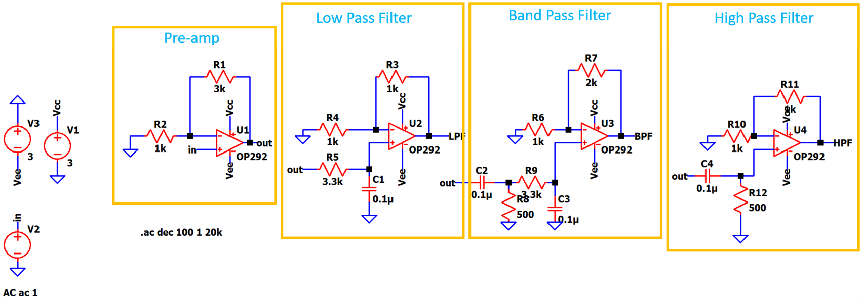
In the last blog, I briefly introduced the active low pass filter circuit. Considering the same circuit and as decided from the above table, Band 1 means a cutoff freq. of 480 Hz, which means fc = 1/(2*pi*R*C) = 480 Hz. Since we have a huge range of standard resistors available but the range of capacitors is limited, a standard value of C is chosen which is 0.1 uF. 

By doing the calculations, the value of R is found to be 3315.72 ohms, so the closest standard value for R is chosen as 3.3 kohms.

Hence, design values for the active LPF are R = 3.3k and C = 0.1 uF. This gives the cutoff freq. of 482 Hz which is quite near to the actual cutoff freq.

Now, to set the gain of the filter, a nominal gain of about 2-3 works fine. For calculating the resistor values for gain, the simple gain formula for non-inverting opamp is used.

Active Band Pass Filter

Next, a band pass filter is designed. A band pass filter filters out a band of frequencies which means it has two cutoff freqs, the lower cutoff (fc1) and the higher cutoff (fc2). Here, from the table, fc1 = 480 Hz and fc2 = 3 kHz.

Hence, using the same formula of LPF, the R and C values for fc1 and fc2 are found to be R1 = 500 ohms and C1 = 0.1 uF and R2 = 3.3k and C2 = 0.1uF. This will give the values of fc1 = 3.18 kHz and fc2 = 482 Hz. 

Active High Pass Filter

For the last block, a high pass filter is designed. The formula remains the same. The fc for HPF from the table is fc = 3kHz. The values for R and C are decided as R = 500 ohms and C = 0.1 uF.

Simulation Results                

I simulated the entire circuit in LT spice to check if it works properly. The simulation setup is AC analysis to check the filter response. The opamps work on a dual rail power supply of +/- 3V. For simulating the audio signal, I have used an AC source.

The below image shows the final circuit diagram along with the individual blocks labeled.
image

The preamp gives a voltage gain of 4 (non-inverting configuration) and the signal from the output of this preamp is then fed to three filter blocks. The outputs of these filters are connected to LEDs(not shown in Ltspice).

Below are the simulation results -

image

It can be seen from the frequency response plots, that the filters are working correctly. If we compare the results of the active LPF with the passive LPF from my last blog, it can be seen that here the gain of the active LPF is around 18dB whereas in the case of the passive filter it was around 0dB due to the lossy filter components and no active components to amplify the filtered signal. The same is the case for other filters too.

Another thing to note is that due to the presence of two resistors in BPF, the gain is less due to loss in resistors. This can be compensated by adjusting the gain of the opamp of the BPF block.

In the next blog, I will construct the circuit on a breadboard and publish the results along with the video. Stay tuned!

  • Sign in to reply

Top Comments

  • jc2048
    jc2048 over 3 years ago in reply to rsjawale24 +1
    Could it be that your 'Pre-amp' section needs a dc path to the non-inverting input? If it is being fed from a source through a coupling capacitor, the op-amp side of the capacitor charges on any leakage…
  • dang74
    dang74 over 3 years ago

    I like this project.  Experimenting with some audio projects of my own is on my to do list.... along with a number of other things I may or may not get around to, LOL.

    • Cancel
    • Vote Up 0 Vote Down
    • Sign in to reply
    • More
    • Cancel
  • rsjawale24
    rsjawale24 over 3 years ago in reply to jc2048

    Thanks! I tried to feed the filter directly without the preamp, still, I'm getting the same results. I'll write a new blog soon and update all the results as well as the problems I'm facing. I'm a little surprised as this should work without any difficulty. Maybe I'm making a mistake somewhere. This is definitely going to be a good learning experience for me.

    • Cancel
    • Vote Up 0 Vote Down
    • Sign in to reply
    • More
    • Cancel
  • jc2048
    jc2048 over 3 years ago in reply to rsjawale24

    Could it be that your 'Pre-amp' section needs a dc path to the non-inverting input? If it is being fed from a source through a coupling capacitor, the op-amp side of the capacitor charges on any leakage from the op-amp (whatever that might happen to be) and the preamp output could end up anywhere in dc terms. Quick way to find out would be to put a 10k resistor from the point marked 'in' to ground. That then pulls the average dc input to near zero. It will easily overcome any small leakage current, but is still easy enough to drive from any sensible piece of audio equipment.

    • Cancel
    • Vote Up +1 Vote Down
    • Sign in to reply
    • More
    • Cancel
  • rsjawale24
    rsjawale24 over 3 years ago in reply to DAB

    Unfortunately, it's not working. I'm not sure what is wrong. Conceptually, it should work. For the LEDs at LPF, they remain always ON and for HPF LEDs always stay OFF. I tried debugging, but I do not have the required test and measurement instruments

    • Cancel
    • Vote Up 0 Vote Down
    • Sign in to reply
    • More
    • Cancel
  • DAB
    DAB over 3 years ago

    It will be interesting to see if your build comes close to your simulation results.

    • Cancel
    • Vote Up 0 Vote Down
    • Sign in to reply
    • More
    • Cancel
element14 Community

element14 is the first online community specifically for engineers. Connect with your peers and get expert answers to your questions.

  • Members
  • Learn
  • Technologies
  • Challenges & Projects
  • Products
  • Store
  • About Us
  • Feedback & Support
  • FAQs
  • Terms of Use
  • Privacy Policy
  • Legal and Copyright Notices
  • Sitemap
  • Cookies

An Avnet Company © 2025 Premier Farnell Limited. All Rights Reserved.

Premier Farnell Ltd, registered in England and Wales (no 00876412), registered office: Farnell House, Forge Lane, Leeds LS12 2NE.

ICP 备案号 10220084.

Follow element14

  • X
  • Facebook
  • linkedin
  • YouTube