


 | Enter Your Project for a chance to win a grand prize for the most innovative use of Arduino or a $200 shopping cart! The Birthday Special: Arduino Projects for Arduino Day! | Project14 Home |
| Monthly Themes | ||
| Monthly Theme Poll |

Do you have a home automation system, and would like a simple and unobtrusive way for it to communicate with you? Would you like that communication to also be an attractive part of your decor? Have we got a project for you!
This project will show you how to build a wifi-connected decoration for your home which is also part of your IoT smart home. What is detailed here is just one example - how yours looks is limited only by your creativity!

https://www.youtube.com/watch?v=nAlJKaAYjTw
What does this thing do?
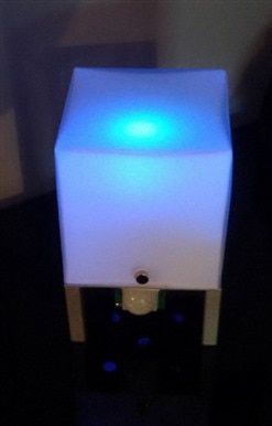
Normally, when your smart home system does not have any messages for you, the ball just glows different colours. The colour fades from red to blue to green to red (and all the colours in between) and so on. It also sends your system regular updates on the ambient temperature and humidity, the light levels, and whether it has detected any movement.
When certain events occur, things change (assuming you have configured these functions...we will show you how here). If your system sends an "alarm" alert, the ball slowly flashes red (fading from black to red and back to black again). If your phone gets an alert, it will flash blue, and a doorbell will cause it to flash green.
If that is not enough to keep you interested, you can switch the ball to manual mode and choose a colour and brightness level.
And don't worry about it keeping you up at night either! When evening comes it turns itself off so you will not go nuts from the glowing lights (you can place multiple magic balls throughout the house).
How does this thing work, magic?
Almost! It uses code written in the Arduino IDE and running on the wifi-capable ESP8266 board.
What do I need to build the "Magic Ball":
An ESP8266 Development Board (ie NodeMCU)

An RGB LED:

A DHT 11 (or DHT22) temperature and Humidity module:

A light sensor (light sensitive resistor):
A PIR Infra Red motion sensor (D-Sun model used here):

Some resistors:
2 100 OHM resistors
1 150 OHM resistors
1 10 KiloOHM resistor (10,000 ohm)
Some female jumper wires to connect things up:

Some heat shrink tubing.
Micro USB cable and wall adapter to power the board.
A soldering iron and solder.
If you do not want to do any soldering, you can use a small breadboard instead. Just make sure you have room in your enclosure
Something nice to put it all in! For our example I used a ball and box I found at my local dollar store. You can really use anything which is the right size and which looks nice lit up (even 3D printed objects!).
How do I make it?
Let's start by getting the LED ready. For this step you will need:
4 pieces of header wire. i used a red one, green one, blue one, and white (or black) one to make it easier to keep track of which wires lights up which colour.
The 3 resistors.
The RGB LED.
Some heat shrink tubing.
Soldering iron and solder.
The RGB LED has 4 leads coming out of it. The longest one is the common (ground or negative) pin. If you look at them with the second pin being the long (common) then they will each be: red, common, green, blue
You want to cut short pieces of header wire with a female connector on one end - about 8 cm or so each. Strip the ends to get them ready to solder.
Solder the white wire directly to the common (long) lead.
Solder one lead of the 150 ohm resistor to the red lead, and the other end to the red jumper wire. Do the same for the other 2 colours, but use the 100 OHM resistors for these.
Protect you connections with the heat shrink tubing (or electrical tape). When you are done it should look something like this:

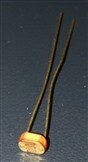
Next, let's get the light-sensitive resistor ready.
For this you will need:
The photo-resistor
3 Header wires (different colours) - I will use grey, brown, and orange here.
The 10K OHm resistor.
Soldering iron and solder.
Heat shrink tubing.
Prep the header wires just like you did for the RGB LED.
Solder one end of the grey wire to one lead of both the photoreistor, and the 10k resistor. Solder each of the other wires to the remaining leads of the photoresistor and resistor.
Here is a simple diagram:

In this case the brown is for 3.3V, the grey is the analog output, and the orange is ground.
When you are done it should look something like this:

Now we can hook everything up!
The RGB LED will connect like this:
The white (or black) wire should be connected to a ground (GND) pin on the ESP8266.
The red wire connects to pin D5.
Green connects to pin D6.
Blue connects to pin D8
For the photo-resistor:
the grey wire connects to pin A0
The orange wire to another GND pin.
The brown wire connects to a 3V pin (this is 3.3volts).
For the DHT11:
+ goes to a 3V pin.
- goes to a GND pin.
out goes to pin D1.
Finally, for the PIR:
VCC goes to the VU pin.
GND goes to another GND pin.
out goes to pin D0.
You should arrange the sensors in your enclosure so that:
- The DHT11 and the photo-resistor are on the outside, preferably out the back where it will not be seen.
- The motion sensor is pointing towards the area you want to track.
- the RGB LED will light up whatever feature you decided on.
Here is how it looks in my example:


And here is the same hardware in a lamp I found in a thrift store - I gutted the light and put my own stuff in it:
Next, let's put the firmware on the ESP8266:
If you do not have the Arduino IDE installed with the ESP8266 extensions, follow the instructions here:
Arduino IDE install:
https://www.arduino.cc/en/Main/Software
ESP8266 setup for Arduino IDE:
Quick Start Guide to Arduino IDE With NodeMCU ESP8266
Once you have that set up, download my firmware here:
https://drive.google.com/open?id=1XFdaD3NfR2Q98Fs1UvdHhbKxA8tI3WAm
Load this file in your Arduino IDE and edit the following:
- Lines 10 and 11 are where you enter your Wifi name and password.
- Lines 13 and 14 have your MQTT user and password
- Lines 16 to 26 contain the MQTT topics which need to be adjusted for each ball you hook up (mbr stood for master bedroom...)
- Line 37 is where the IP address lives for your MQTT server
- You also need to edit line 186. The "MBedroom" is a unique ID for each ball. Change this to whatever you want to call it.
Make sure you set the correct com port and board in Arduino IDE, and Upload the file to the board.
Tada! If all went well you should have a glowing ball which is slowly changing colour.
If you want to add the extra functionality, here are the files I used for OpenHAB2:
https://drive.google.com/open?id=1RlXocLMxUtZlgUaTXwlU2q4FVd5ca9Az
https://drive.google.com/open?id=12XkoreE90kwLGSRHHMnpUdvqSaWALI7p
https://drive.google.com/open?id=1rM06EdycxI6rPsqVtV3t3qOR3-z0azbU
Setting up OpenHAB2 is beyond the scope of this blog post, but stay tuned to my channel and there will be a howto coming: