element14 Community
element14 Community
    Register Log In
  • Site
  • Search
  • Log In Register
  • Community Hub
    Community Hub
    • What's New on element14
    • Feedback and Support
    • Benefits of Membership
    • Personal Blogs
    • Members Area
    • Achievement Levels
  • Learn
    Learn
    • Ask an Expert
    • eBooks
    • element14 presents
    • Learning Center
    • Tech Spotlight
    • STEM Academy
    • Webinars, Training and Events
    • Learning Groups
  • Technologies
    Technologies
    • 3D Printing
    • FPGA
    • Industrial Automation
    • Internet of Things
    • Power & Energy
    • Sensors
    • Technology Groups
  • Challenges & Projects
    Challenges & Projects
    • Design Challenges
    • element14 presents Projects
    • Project14
    • Arduino Projects
    • Raspberry Pi Projects
    • Project Groups
  • Products
    Products
    • Arduino
    • Avnet & Tria Boards Community
    • Dev Tools
    • Manufacturers
    • Multicomp Pro
    • Product Groups
    • Raspberry Pi
    • RoadTests & Reviews
  • About Us
  • Store
    Store
    • Visit Your Store
    • Choose another store...
      • Europe
      •  Austria (German)
      •  Belgium (Dutch, French)
      •  Bulgaria (Bulgarian)
      •  Czech Republic (Czech)
      •  Denmark (Danish)
      •  Estonia (Estonian)
      •  Finland (Finnish)
      •  France (French)
      •  Germany (German)
      •  Hungary (Hungarian)
      •  Ireland
      •  Israel
      •  Italy (Italian)
      •  Latvia (Latvian)
      •  
      •  Lithuania (Lithuanian)
      •  Netherlands (Dutch)
      •  Norway (Norwegian)
      •  Poland (Polish)
      •  Portugal (Portuguese)
      •  Romania (Romanian)
      •  Russia (Russian)
      •  Slovakia (Slovak)
      •  Slovenia (Slovenian)
      •  Spain (Spanish)
      •  Sweden (Swedish)
      •  Switzerland(German, French)
      •  Turkey (Turkish)
      •  United Kingdom
      • Asia Pacific
      •  Australia
      •  China
      •  Hong Kong
      •  India
      • Japan
      •  Korea (Korean)
      •  Malaysia
      •  New Zealand
      •  Philippines
      •  Singapore
      •  Taiwan
      •  Thailand (Thai)
      • Vietnam
      • Americas
      •  Brazil (Portuguese)
      •  Canada
      •  Mexico (Spanish)
      •  United States
      Can't find the country/region you're looking for? Visit our export site or find a local distributor.
  • Translate
  • Profile
  • Settings
Portable Electronics Kit
  • Challenges & Projects
  • Project14
  • Portable Electronics Kit
  • More
  • Cancel
Portable Electronics Kit
Blog EE-CARD: A Portable Electronics Project Kit
  • Blog
  • Forum
  • Documents
  • Events
  • Polls
  • Files
  • Members
  • Mentions
  • Sub-Groups
  • Tags
  • More
  • Cancel
  • New
Join Portable Electronics Kit to participate - click to join for free!
  • Share
  • More
  • Cancel
Group Actions
  • Group RSS
  • More
  • Cancel
Engagement
  • Author Author: shabaz
  • Date Created: 16 Jan 2018 8:25 PM Date Created
  • Views 3864 views
  • Likes 20 likes
  • Comments 30 comments
  • training system
  • prototyping system
  • project_14
  • project14
  • project 14
  • ee-card
  • portableekitch
Related
Recommended

EE-CARD: A Portable Electronics Project Kit

shabaz
shabaz
16 Jan 2018

Introduction

This project is about a new portable electronics prototyping kit : ) It is modular, and the first module is concerned with resistors and capacitors.

image


When I was a kid, I had a Tandy/Radio Shack 160-in-one electronics kit, and it allowed me to try out hundreds of projects.  The kit I had used springs and wires. The components were all fixed on a base board, and the wires would be patched using the springs, in order to construct a circuit.
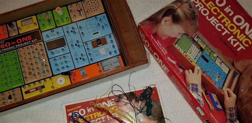
image

Image source: ebay


I wanted to create a modern version with modern parts : ) Nowadays wires are often patched using jumper wires into plastic breadboards. Breadboards are cheap, so I wanted to find some way to integrate them into the system.

image

Image source: FarnellFarnell


The appearance was also an important factor; I wanted the system to look as interesting as I could make it, to encourage interest from beginners. A building block style design sounded attractive.


Modern components are surface-mount, so I wanted the system to allow project prototyping using them in some way, and get people familiar with how modern components look.

Finally, I wanted to create some ecosystem, or expandable system, that could grow over time.


This blog post documents my attempts.


History

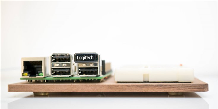
Several years ago, I attached a Raspberry Pi and a breadboard onto a block of wood. I still use this combination. It is simple but really convenient for rapidly prototyping. I can connect jumper wires directly from the Pi's 40-way connector, and connect them to any circuit created on the adjacent breadboard.

image


Then, about a year ago, I was experimenting with a BeagleBone Black, and I wanted to do a similar thing, but this time also attach a character display, for showing brief status information. But, the display was expensive, and I didn’t want to permanently attach it to the BeagleBone Black. After thinking for a while, I decided to create some sort of modular system where the display could be clicked into position.

image

I chose a red and black color scheme to suit the BeagleBone Black Industrial card.


While I was at it, I made the breadboard into a clickable module too. It worked quite well.

image

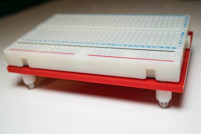
The plastic standoffsplastic standoffs click into position onto the black baseboard, and can be easily unplugged too. If you want to make this, it is really easy. Red 3mm perspex/acrylic is chopped up and the edges are sanded to a smooth finish, and some holes are drilled for the stand-offs (countersunk screws from the top side are used to secure the stand-offs). The breadboard is permanently stuck on.


The new EE-CARD Training System!

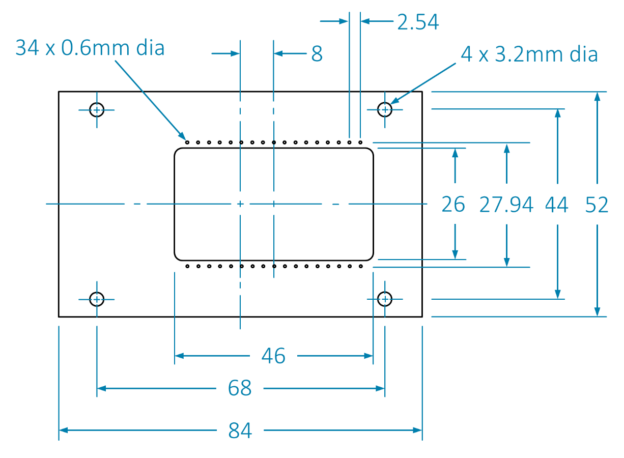
Moving forward to today, I wished to expand the system further, and make it into a general project kit. I decided to stick to the dimensions that I’d chosen for the breadboard; I’d used a credit card size of 84x52mm and a narrower size for the display. My dilemma was how to continue this type of system but try to replicate the old Radio Shack style project kits with the baseboard with the components on it! I really liked it, because the components couldn’t really be lost; they were permanently attached to the baseboard, and they were clearly labelled!


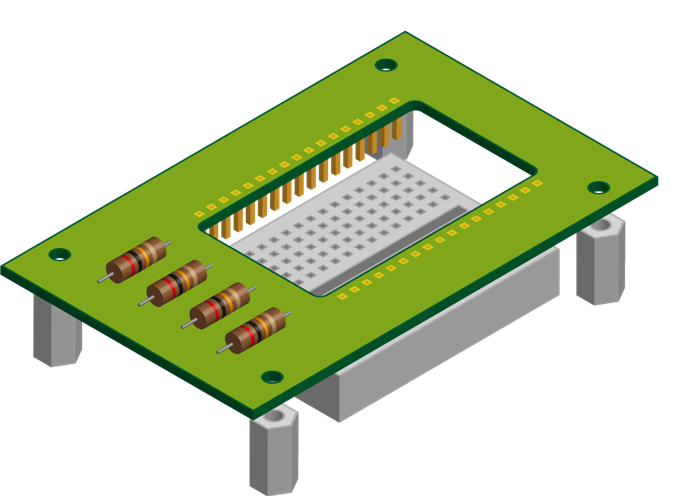
I decided to use a printed circuit board to imitate that old system. I could solder parts to it, and have them clearly labelled on the silkscreen print. The problem was how to integrate it with the breadboard. In the end, I decided to go with quite a simple approach. See the diagram here for the idea. A low-cost 170-hole breadboard is pushed in from the underside and permanently left attached to each EE-CARD. Wire connections are made from one EE-CARD to another using the breadboard space.

image


What Features?

For the initial functionality, it was clear that a board with resistors and capacitors would be mandatory. I chose some popular values, which should be sufficient for creating dozens of small circuits. Often the precise value isn’t as important as getting a resistance in a ballpark, so I was not too fussed that all popular resistor values were not represented.  The Tandy/Radio Shack 160-in-one kit only has 12 resistors, and it provides for 160 projects : )


For some of the other EE-CARDs, a semiconductor board carrying some transistors and diodes and an op amp would be handy. A logic board could carry some gates and a 555 acting as an oscillator. A control board would have some buttons and LEDs. Maybe a microcontroller EE-CARD could also be created. Basically I feel the credit-card sized form-factor allows for quite a lot of functionality.


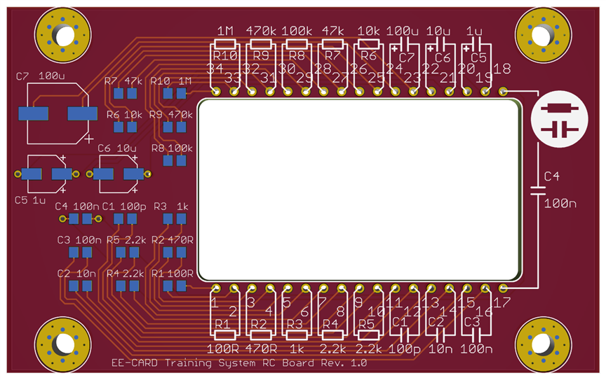
I set to work in EAGLE, creating the basic outline that would be used for all the boards, and then creating many copies of the design and adding the specific functionality. The first board rendering is shown here; I still need to do the others.


I tried to create a style that could be used for the future boards with some consistency; there is a graphic element on the top-right that quickly shows which board is picked up. At the bottom of the board there is also a text description, and board revision number.

image


Building It

To be continued : ) I will update this blog post when the PCBs are made in a few weeks time. In the meantime, if you wish to also replicate this project, the CAD files will be attached below as they are created, ready for sending to a PCB factory.


Designing your own EE-CARDs

It would be great to hear about custom EE-CARDS designed by others one day.

image


Summary

The basics of a modular, expandable portable prototyping system was presented, called the EE-CARD. The boards are credit-card sized, and allow for direct wire patching to create circuits. The EE-CARDS have pegs allowing them to be positioned in different combinations onto a base board with holes in it.

  • Sign in to reply

Top Comments

  • shabaz
    shabaz over 8 years ago in reply to tankman +7
    Tandy/Radio Shack definitely helped shape the future of budding engineers with their kits and notebooks. We didn't have Heathkit's in the UK while I was growing up as far as I'm aware, but I recall seeing…
  • rachaelp
    rachaelp over 8 years ago +6
    Nice! I had a very similar 160-in-1 electronics kit when I was young and strangely I was thinking about that and wondering about if there was a modern equivalent just the other day and here you are designing…
  • shabaz
    shabaz over 8 years ago in reply to jw0752 +6
    In that case - if I ever make one, I'll make two of each part. It can have a twin in Wisconsin : )
  • shabaz
    shabaz over 8 years ago in reply to tankman

    Tandy/Radio Shack definitely helped shape the future of budding engineers with their kits and notebooks. We didn't have Heathkit's in the UK while I was growing up as far as I'm aware, but I recall seeing this Heathkit robot photo in books and wanting one!

    If I ever learn how to use a 3D printer properly, I'll probably have to take a stab at making one!

    image

    • Cancel
    • Vote Up +7 Vote Down
    • Sign in to reply
    • More
    • Cancel
  • tankman
    tankman over 8 years ago

    I had one of these proto-kits, then later a Heathkit Amateur radio rcvr and transmitter (huge)

    where I learned electronics and soldering.

    With the radio shack kits there were some "application notebooks" that had circuits showing how to component by component build them. It explained what the resistors, capacitors were, how they worked in the system and how to assemble the circuit.  Very helpful for my early tinkering.
    I think that would be beneficial to self starters with little to no knowledge to begin with.

    • Cancel
    • Vote Up +2 Vote Down
    • Sign in to reply
    • More
    • Cancel
  • beacon_dave
    beacon_dave over 8 years ago in reply to rachaelp

    I had the Philips 'Radionics x40' set which had each component mounted onto a plastic base which then had two (or three) brass bolts sticking out of the bottom of it. This then was pushed into a universal PCB and then nuts and washers attached to the back instead of solder.


    It worked, however the bolts were longer than they needed to be and the nut spinner provided was a bit crude, so it took forever to assemble the circuit and you ended up with blisters in the palm of your hand and your fingers ached.


    Then you had to undo them all in order to build the next circuit.


    Another downside to it was that because it was a PCB which had been designed specifically for the project book supplied with it, it meant that it was difficult to build anything apart from the supplied designs.


    One shortfall, which Shabaz may have solved here was with these kits you had nothing to show for your efforts at the end of the day. With an Airfix model you had a plane or a ship to put on display, which is the same for a lot of hobbies. With Shabaz's concept there looks to be an option to replace the breadboard with protoboard once you have got the prototype to work allowing for a more permanent design. Perhaps could come up with a box for it even.

    • Cancel
    • Vote Up +3 Vote Down
    • Sign in to reply
    • More
    • Cancel
  • shabaz
    shabaz over 8 years ago in reply to jw0752

    Hi John,


    Thanks! I hope we all have a really productive year : )

    • Cancel
    • Vote Up 0 Vote Down
    • Sign in to reply
    • More
    • Cancel
  • jw0752
    jw0752 over 8 years ago

    Hi Shabaz,

    You are off to an excellent start on great projects for 2018. I love the idea of bringing the 160 in one into the 21st century.  You will need a voltage converter module so one battery can provide +/- variable voltages for your circuits.

    John

    • Cancel
    • Vote Up +4 Vote Down
    • Sign in to reply
    • More
    • Cancel
<>
element14 Community

element14 is the first online community specifically for engineers. Connect with your peers and get expert answers to your questions.

  • Members
  • Learn
  • Technologies
  • Challenges & Projects
  • Products
  • Store
  • About Us
  • Feedback & Support
  • FAQs
  • Terms of Use
  • Privacy Policy
  • Legal and Copyright Notices
  • Sitemap
  • Cookies

An Avnet Company © 2026 Premier Farnell Limited. All Rights Reserved.

Premier Farnell Ltd, registered in England and Wales (no 00876412), registered office: Farnell House, Forge Lane, Leeds LS12 2NE.

ICP 备案号 10220084.

Follow element14

  • X
  • Facebook
  • linkedin
  • YouTube