


What is FPGA? (source: Wikipedia)
A field-programmable gate array (FPGA) is an integrated circuit designed to be configured by a customer or a designer after manufacturing – hence the term "field-programmable". The FPGA configuration is generally specified using a hardware description language (HDL), similar to that used for an Application-Specific Integrated Circuit (ASIC). Circuit diagrams were previously used to specify the configuration, but this is increasingly rare due to the advent of electronic design automation tools.

FPGAs contain an array of programmable logic blocks, and a hierarchy of "reconfigurable interconnects" that allow the blocks to be "wired together", like many logic gates that can be inter-wired in different configurations. Logic blocks can be configured to perform complex combinational functions or merely simple logic gates like AND and XOR. In most FPGAs, logic blocks also include memory elements, which may be simple flip-flops or more complete blocks of memory.[1] Many FPGAs can be reprogrammed to implement different logic functions,[2] allowing flexible reconfigurable computing as performed in computer software.
My Aim:
I wanted to do something useful with FPGA as I had Adruino MKR Vidor laying around which I had received for a past contest. The Vidor is still not so beginner friendly but its Graphics Library is still awesome. Also, I had almost forgotten it has WiFi and a microcontroller also. So, I wanted to make something which uses all of the microchips and which can be used on a day-to-day basis. So, the direct thought came was to do something with display because the Vidor has an HDMI (micro) port and also a great library.
Project:
For the project, I thought of making a digital clock- which shows time in analog format and it will also show the date and other information. This will test out my trigonometry skills as well as it can use the internet. Here's how it works...
Working:
The Vidor connects to the internet with the help of its WiFi chip (Esp32) and gets the time in the world via NTP Server. Then the time is stored in the RTC of SAMD21 microcontroller. That time is then displayed in analog format with the date on an HDMI monitor. After the day is over it will automatically sync the time with the NTP Server again and hence it will also remain very accurate.
The output on Monitor is done by Intel Cyclone FPGA onboard.
Code:
//Code By Vimarsh  T@Vimarsh244

#include "VidorGraphics.h"
#include "Vidor_GFX.h"
#include <SPI.h>
//#include <WiFi101.h>
#include <WiFiNINA.h> //Include this instead of WiFi101.h as needed
#include <WiFiUdp.h>
#include <RTCZero.h>

RTCZero rtc;
void(* resetFunc) (void) = 0; //declare reset function @ address 0

char ssid[] = "ssid";        // your network SSID (name)
char pass[] = "psk";    // your network password (use for WPA, or use as key for WEP)
//int keyIndex = 0;                           // your network key Index number (needed only for WEP)

int status = WL_IDLE_STATUS;

const int Hr = 5; //change this to adapt it to your time zone //enter number of hours
const int minutes = 30; //change this to adapt it to your time zone //enter number of minutes

Vidor_GFX  vdgfx;
//drawClock();
int x = 0;
int y = 0;
int prev_sec;
int prev_mint;
void setup() {
  Serial.begin(9600);

  //while (!Serial); //disable to run without cxonnrcting to computer.
  wifi_setup();
  // Initialize the FPGA
  if (!FPGA.begin()) {
    Serial.println("Initialization failed!");
    while (1) {}
  }
  String date = String(rtc.getDay()) + "/" + String(rtc.getMonth()) + "/" + String(rtc.getYear());
  int got_sec = (rtc.getHours() + Hr) * 3600 + (rtc.getMinutes() + minutes) * 60 + rtc.getSeconds();
  drawClockFace();
  vdgfx.text.setCursor(50, 50);
  vdgfx.text.setAlpha(255);
  vdgfx.text.setSize(1);
  vdgfx.text.setColor(vdgfx.lightBlue());
  vdgfx.println("Vidor Clock");
  vdgfx.text.setCursor(200, 100);
  vdgfx.text.setSize(2);
  vdgfx.println(date);


  //The old code for the clock moving... Almost worked. Discarded for Hours....
  /*
    void loop()
    {
    for (int mint = 0; mint < 60; mint++) {
      for (int sec = 0; sec < 60; sec++) {
        if (sec  == mint) {
          x = 320 + 80 * sin(mint * 0.1048);
          y = 280 - 80 * cos(mint * 0.1048);
          vdgfx.drawLine(320, 280, x, y, vdgfx.Yellow());
          vdgfx.drawLine(320, 280, x, y, vdgfx.Yellow());
          vdgfx.drawLine(320, 280, x, y, vdgfx.Yellow());
        }
        x = 320 + 130 * sin(prev_sec * 0.1048);
        y = 280 - 130 * cos(prev_sec * 0.1048);
        vdgfx.drawLine(320, 280, x, y, vdgfx.Yellow());

        x = 320 + 130 * sin(sec * 0.1048);
        y = 280 - 130 * cos(sec * 0.1048);
        vdgfx.drawLine(320, 280, x, y, vdgfx.Purple());
        prev_sec = sec;
        if (sec - 1 == mint) {
          x = 320 + 80 * sin(mint * 0.1048);
          y = 280 - 80 * cos(mint * 0.1048);
          vdgfx.drawLine(320, 280, x, y, 5, vdgfx.Purple());
        }

        delay(100);
      }
      x = 320 + 800 * sin(prev_mint * 0.1048);
      y = 280 - 80 * cos(prev_mint * 0.1048);
      vdgfx.drawLine(320, 280, x, y, vdgfx.Yellow());
      vdgfx.drawLine(320, 280, x, y, vdgfx.Yellow());
      vdgfx.drawLine(320, 280, x, y, vdgfx.Yellow());

      x = 320 + 80 * sin(mint * 0.1048);
      y = 280 - 80 * cos(mint * 0.1048);
      vdgfx.drawLine(320, 280, x, y, 5, vdgfx.Purple());
      prev_mint = mint;

    }
    }
  */

  ///Actual moving of clock and all calculation
  for (int sec = got_sec; sec < 3600 * 24; sec++) {

    x = 320 + 130 * sin(prev_sec * 0.1048);
    y = 280 - 130 * cos(prev_sec * 0.1048);
    vdgfx.drawLine(320, 280, x, y, vdgfx.Yellow());

    x = 320 + 90 * sin(prev_sec * 0.1048 / 60);
    y = 280 - 90 * cos(prev_sec * 0.1048 / 60);
    vdgfx.drawLine(320, 280, x, y, vdgfx.Yellow());

    x = 320 + 50 * sin(prev_sec * 0.1048 / (60 * 12));
    y = 280 - 50 * cos(prev_sec * 0.1048 / (60 * 12));
    vdgfx.drawLine(320, 280, x, y, vdgfx.Yellow());

    x = 320 + 130 * sin(sec * 0.1048);
    y = 280 - 130 * cos(sec * 0.1048);
    vdgfx.drawLine(320, 280, x, y, vdgfx.Purple());

    x = 320 + 90 * sin(sec * 0.1048 / 60);
    y = 280 - 90 * cos(sec * 0.1048 / 60);
    vdgfx.drawLine(320, 280, x, y, vdgfx.Black());

    x = 320 + 50 * sin(prev_sec * 0.1048 / (60 * 12));
    y = 280 - 50 * cos(prev_sec * 0.1048 / (60 * 12));
    vdgfx.drawLine(320, 280, x, y, vdgfx.Blue());
    prev_sec = sec;

    delay(1000);
  }
  resetFunc();  //call reset to reset the board
}
void loop() {

}
//void printTime()
//{
//  print2digits(rtc.getHours() + GMT);
//  Serial.print(":");
//  print2digits(rtc.getMinutes());
//  Serial.print(":");
//  print2digits(rtc.getSeconds());
//  Serial.println();
//}
//
//void printDate()
//{
//  Serial.print(rtc.getDay());
//  Serial.print("/");
//  Serial.print(rtc.getMonth());
//  Serial.print("/");
//  Serial.print(rtc.getYear());
//
//  Serial.print(" ");
//}

void drawClockFace() {
  // Fill the screen with a white background
  vdgfx.fillRect(0, 0, 640, 480, vdgfx.Yellow());
  //Draw the clock face
  vdgfx.fillCircle(320, 280, 150 , vdgfx.Green());
  vdgfx.fillCircle(320, 280, 140 , vdgfx.Yellow());
  vdgfx.fillCircle(320, 280, 2 , vdgfx.Green());

  for (int m = 0; m < 360; m = m + 30) {
    int x = 0;
    int y = 0;
    x = 320 + 140 * sin(m * 0.0175);
    y = 280 - 140 * cos(m * 0.0175);
    vdgfx.fillRect(x, y, 4, 4, vdgfx.Purple());
  }
}


//white: yellow
//Light Blue: Green
//Red: Purple

void wifi_setup() {
  // check if the WiFi module works
  if (WiFi.status() == WL_NO_SHIELD) {
    Serial.println("WiFi shield not present");
    // don't continue:
    while (true);
  }

  // attempt to connect to WiFi network:
  while ( status != WL_CONNECTED) {
    Serial.print("Attempting to connect to SSID: ");
    Serial.println(ssid);
    // Connect to WPA/WPA2 network. Change this line if using open or WEP network:
    status = WiFi.begin(ssid, pass);

    // wait 10 seconds for connection:
    delay(10000);
  }

  // you're connected now, so print out the status:
  printWiFiStatus();

  rtc.begin();

  unsigned long epoch;
  int numberOfTries = 0, maxTries = 6;
  do {
    epoch = WiFi.getTime();
    numberOfTries++;
  }
  while ((epoch == 0) && (numberOfTries < maxTries));

  if (numberOfTries == maxTries) {
    Serial.print("NTP unreachable!!");
    while (1);
  }
  else {
    Serial.print("Epoch received: ");
    Serial.println(epoch);
    rtc.setEpoch(epoch);

    Serial.println();
  }
}


void printWiFiStatus() {
  // print the SSID of the network you're attached to:
  Serial.print("SSID: ");
  Serial.println(WiFi.SSID());

  // print your WiFi shield's IP address:
  IPAddress ip = WiFi.localIP();
  Serial.print("IP Address: ");
  Serial.println(ip);

  // print the received signal strength:
  long rssi = WiFi.RSSI();
  Serial.print("signal strength (RSSI):");
  Serial.print(rssi);
  Serial.println(" dBm");
}

void print2digits(int number) {
  if (number < 10) {
    Serial.print("0");
  }
  Serial.print(number);
}
Actually, I have also kept my old code as comments if you are interested. Regarding the trigonometric functions sin and cos have always remained favourable and they perfectly help in assigning coordinate. In my code, some colours are changed that is because in my Vidor (or due to adapter) some colours are represented differently. Though I have mentioned which colour is changed to which.
The loop of the code does not have any commands because it is never executed. In setup the Vidor gets the time and runs a loop to complete a day and then it resets automatically so that it can calibrate itself. Initial little code is taken from here
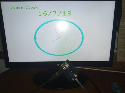
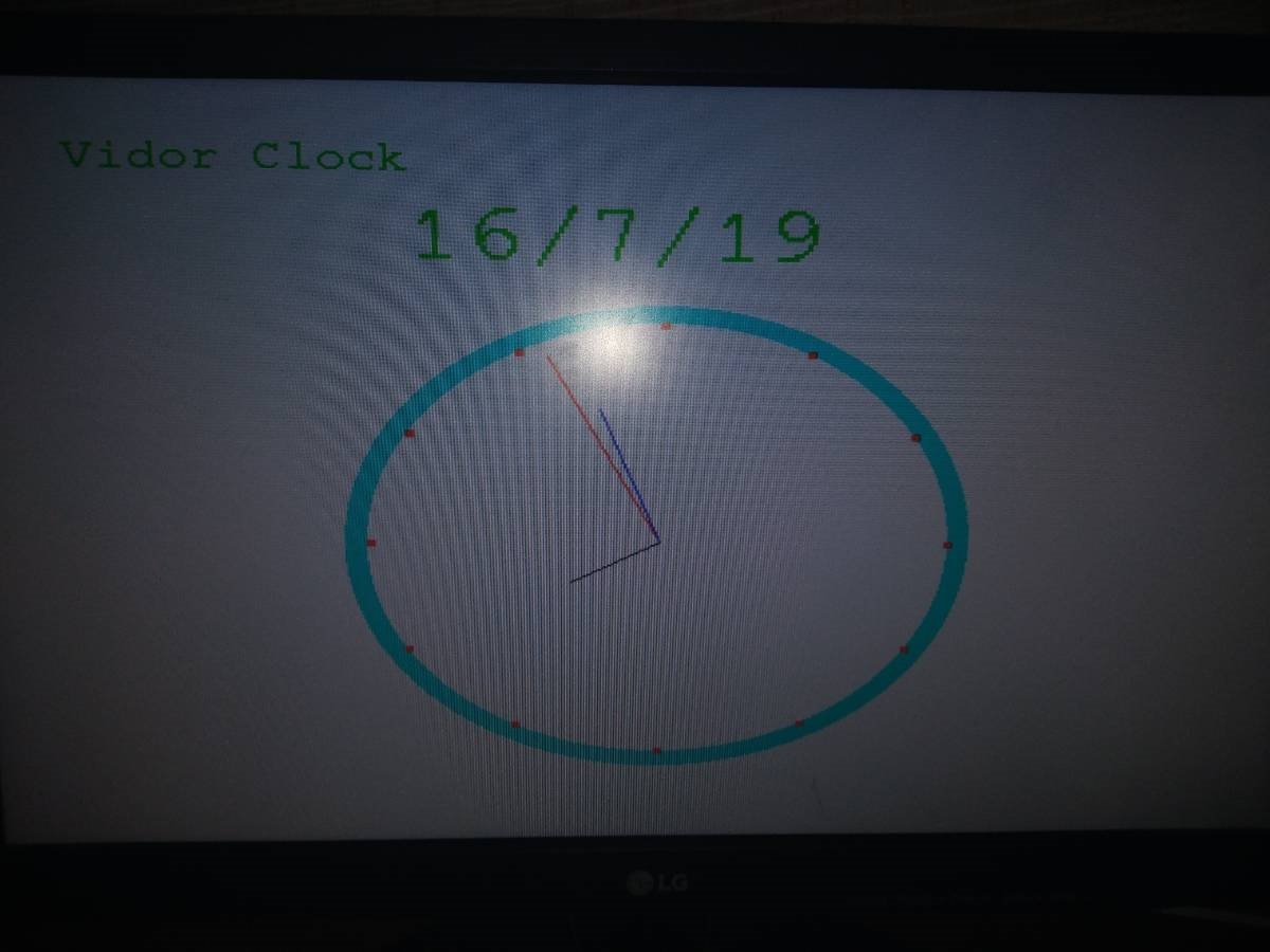
Demonstration:
Pictures..
| {gallery} Pictures of Project |
|---|
|
A Bug in the code. |
|
A Arduino Logo shown when programming and loading(starting) of Vidor |
|
Time is shown on Monitor. |
|
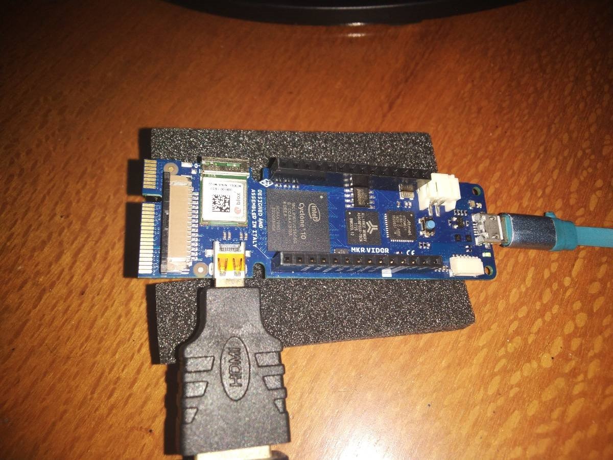
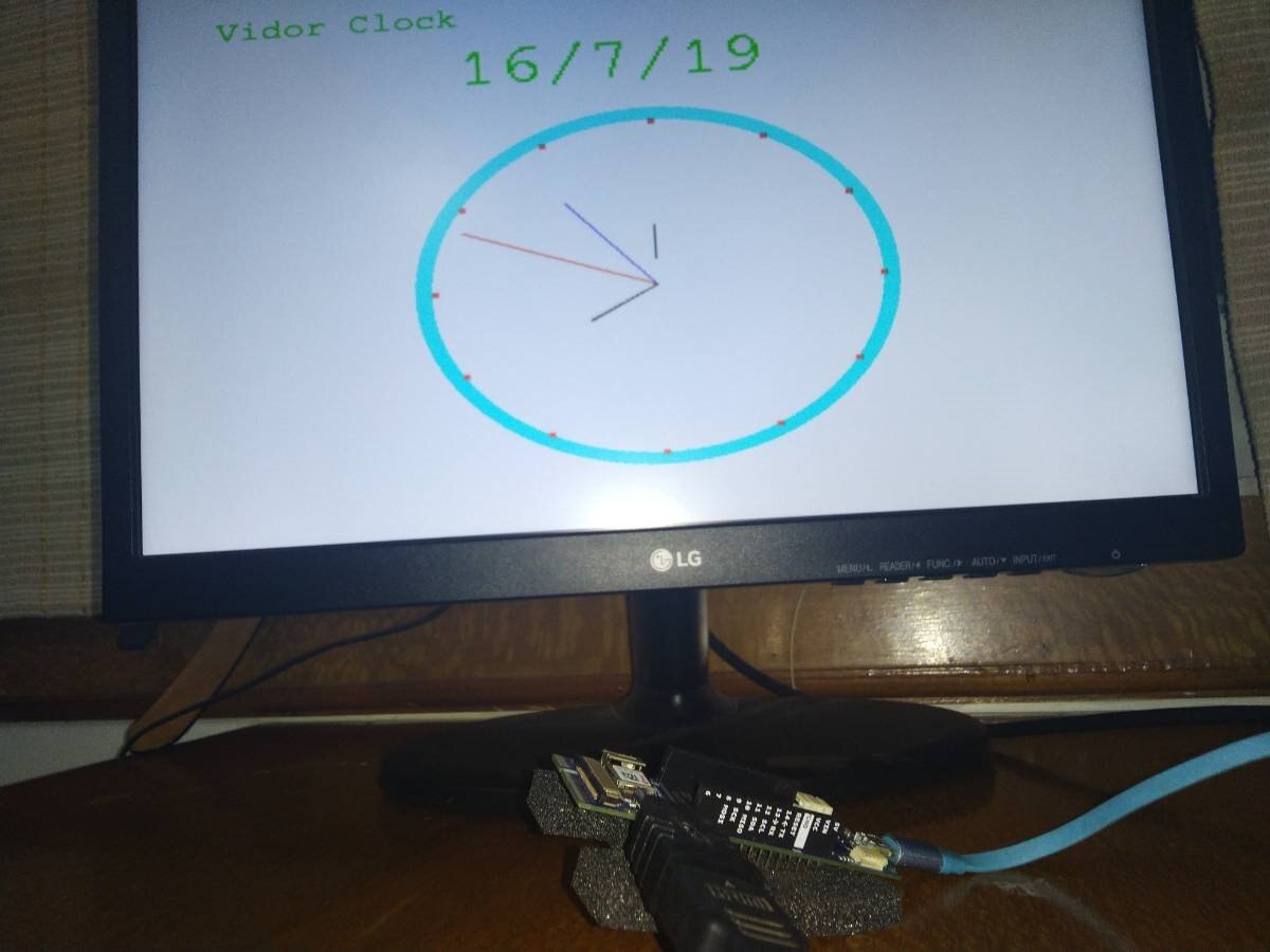
Vidor Connected to Power and Monitor |
|
Vidor Clock in Action |


Video...
Conclusion:
I enjoyed creating this project and learned some new things... Though I would still say most of the advantages of the Cyclone FPGA on Vidor are locked by the complexity of programming it to use it to fullest.
FPGA's are going to be widely adopted in future as they are really good for any task you give be it Edge computing, Recognition, Interfacing, IoT, and lots more.


