Introduction
In Engineering resistors one of the very common and one of the most essential components which are very widely used. The resistances of through-hole resistors can be calculated using colour code, while for other components and SMT components as well as calculating resistance is required in various situations. This is traditionally done by calculating the current and voltage through it to evaluate the resistance, but in practical conditions, this is not always very feasible to measure these parameters and calculation is also a tedious job. Thus there is a need for a simple, time saving & cost-efficient solution to solve this need and make our task easy.
Solution
The proposed solution is to make a simple device that can calculate measure unknown resistances of circuits & components, using known reference resistors, Arduino or any other MCU for signal processing/calculations. Therefore by making this project there is an attempt to make an “OHM-Meter” which would help calculate the resistance of any required component/circuit at one go using it.
Materials Required
Hardware :
- Arduino (any MCU can be used)
- Resistors Box (containing resistors of various ranges)
- Jumper Wires
- Breadboard (optional)
- USB Type B Cable
- Power Source
- Laptop/PC for observing the readings (LCD display can be used as an alternative)
Software :
- Arduino IDE
- Resistor Value calculation using Colour Coding
- The resistor is a passive component within an electrical or electronic circuit is to “resist”, regulate or to set the flow of electrons (current) through them by using the type of conductive material from which they are composed. The resistors used for this project are ¼W 4-band resistors, as it can be seen in the diagram below the first two bands represent nominal value, the third band represents multiplier and the fourth represent the tolerance.
- Using Arduino & Arduino IDE
- The Arduino IDE uses Embedded C/ C++ based language for programming the Microcontroller, while the Arduino is helpful for taking various inputs and perform various functions/calculations to give an output (both input and output are in terms of voltages).
- OHM’s Law
- Ohm's law states that the current through a conductor between two points is directly proportional to the voltage across the two points. Introducing the constant of proportionality, the resistance, one arrives at the usual mathematical equation that describes this relationship ( V = I * R )
- KVL
- Kirchhoff's Voltage Law (2nd Law), states that “in any closed-loop network, the total voltage around the loop is equal to the sum of all the voltage drops within the same loop” which is also equal to zero.
- Voltage Divider
- A voltage divider (also known as a potential divider) is a passive linear circuit that produces an output voltage (Vout) that is a fraction of its input voltage (Vin). Voltage division is the result of distributing the input voltage among the components of the divider.
- Wheatstone Bridge
- A simple circuit for measuring an unknown resistance by connecting it so as to form a quadrilateral with three known resistances and applying a voltage between a pair of opposite corners. The fundamental property of the circuit is that the two points B & D are at equipotential, due to the resistors having the same ratio, thus the current flowing in the bridging resistor is zero.
- Arduino
- Arduino Uno development board based on ATMega328p microcontroller (MCU) that can measure voltages and also give output voltages, and you can program it to calculate and perform signal processing. Arduino is an open-source electronics platform based on easy-to-use hardware and software. Arduino senses the environment by receiving inputs from many sensors and affects its surroundings by controlling lights, motors, and other actuators. It has 14 digital input/output pins (of which 6 can be used as PWM outputs), 6 analog inputs, a 16 MHz ceramic resonator, a USB connection, a power jack, an ICSP header and a reset button. It operates on 5V logic levels, and per I/O pin current drawn is 20mA, flash memory of 32kb, 2kb SRAM, 1kb EEPROM and is an 8-bit (1024 parts accuracy) microcontroller.
- The Arduino Integrated Development Environment (IDE) is a cross-platform application that is written in functions from C and C++. It is used to write and upload programs to Arduino compatible boards, but also, with the help of third-party cores, other vendor development boards. The editor can be used to make programs and debug them and also take reading/output in the Serial Monitor of the Arduino IDE.
- Resistors
- A resistor is a passive two-terminal electrical component that implements electrical resistance as a circuit element. In electronic circuits, resistors are used to reduce current flow, adjust signal levels, to divide voltages, bias active elements, and terminate transmission lines, among other uses. High-power resistors that can dissipate many watts of electrical power as heat, may be used as part of motor controls, in power distribution systems, or as test loads for generators. Fixed resistors have resistances that only change slightly with temperature, time or operating voltage.
Principle & Explanation behind Working of the trivial resistance measuring
The working of this OHM-Meter uses fundamental laws and concepts like the OHM’s Law, KVL & voltage divider. The below voltage divider circuit is the basic way used to measure unknown resistances, here we are considering R1 is unknown while R2 is known, as we know that in this voltage divider the drop measured across R2 is proportional to the ratio of R1 & R2, this can be seen by applying KVL(voltage drop by both resistors would be equal to the input voltage) in the loop Vin =(I*R1+I*R2) → I =Vin/(R1+R2) , then by applying OHM’s Law → Vout = I*R2 → Vout = (Vin*R2)/(R1+R2) , we know values of Vin(given) , Vout(measured)& R2(given) , so we can easily compute the value of R1 the unknown resistance.So trivially the voltage drop of known resistance can be measured with voltameter and then perform reuired calculations to compute the unknown resistance .
Building the OHM - MeterThe below circuit is made and the following code is flashed into the Arduino
Schematic & Code on simulator AutoDesk TinkerCAD
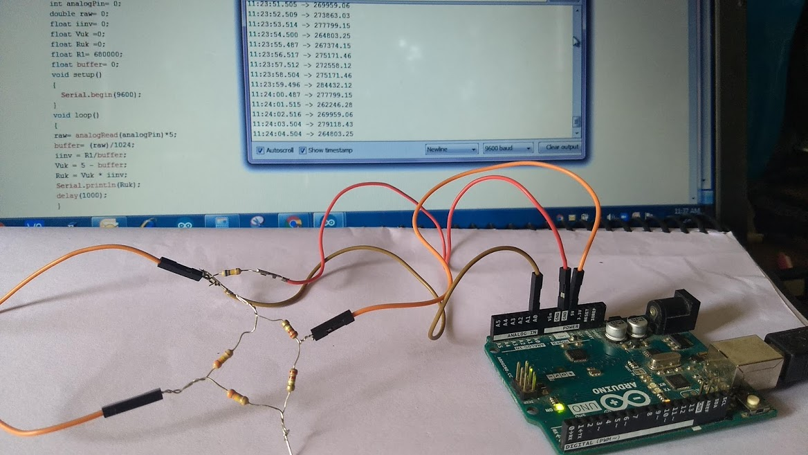
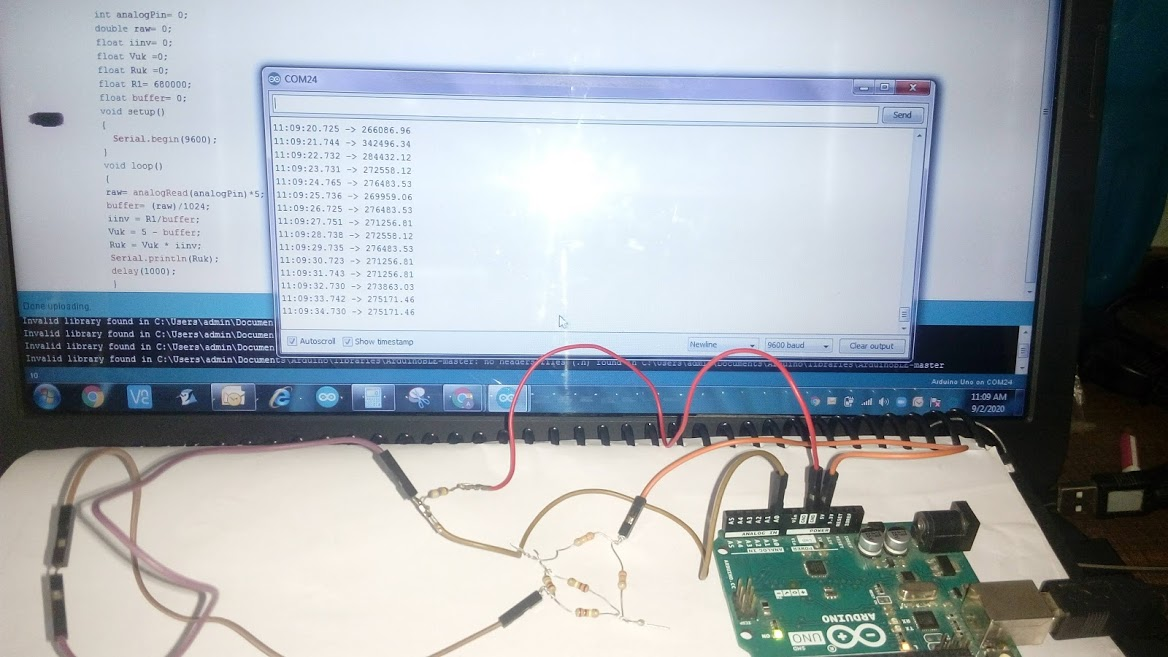
- Actual Circuit and Code ,oberving values & OHM-Meter in action


Code & it’s working
Basically we first initialise variables(known resistance is of 680k ohm) in the code , then we also start the serial communication , First we take the value measurement of voltage drop by Known Resistor through the Analog Pin (A0) , which is in 8 bit relative form (where 1024 represents 5v) , so we multiply with 5v(input) and then divide by 1024 in buffer variable to get the voltage drop , then iinv stores inverse value of current by calculating value using OHM’s Law , the Voltage drop by unknown part is calculated by subrating drop caused by known resistor(buffer) from input voltage(5v) , then the unknown resistance value is computed by using OHM’s law again and dividing voltage from current (ie V/I) by taking product of Voltage of unknown resistor(Vuk) and current inverse(iinv) , we get the value of the unknown resistance and its displayed on serial monitor and reiterate after 1 second.
Verifying the Build with Wheatstone Bridge
In the project to measure the values of unknown resistance we use the wheatstone circuit (it was chosen because it is one of the most common and is widely used for accuarte measurements of unknown resistances),as the unknown circuit to verify the calculated resistance by OHM-Meter is correct or not .(Known Resistance=680k Ohm)R1=220k ohm, R2=220k ohm, R3=220k ohm, R4=330k ohm, R5=330k ohmAs here (R1/R4)=(R2/R5) which satisfies the whetstone bridge condition , which implies the both ends of R3 are at equipotential thus no current flowed through it and it doesnt cause any voltage drop , so we can ignore it while calculating net resistance , the equivalent resistance is Req = ((R1+R4)*(R2+R5))/(R1+R4+R2+R5)On putting values here we get 275k Ohm , while the readings are in approx range of 269k-277k ohm , which verifies that the build is successful and results are pretty accurate.
Results and ConclusionThe results observed in the measurements using OHM-Meter are preety accurate , the error percentage is less than ± 5% which is very good considering that all resistors used here in project also had tolerance of ± 5% ,therefore the obtained results are acceptable for measuring resistances.The conclusion of this projet is that this OHM-Meter can be a very useful tool to measure resistances but also has its limitation that the known resistance that is used for reference for measurement should be in significant range of the known resistance , if the difference is higher between both of them then the error percantages increases drastically.This limitation can be be overcomed two ways
- By using a range of different known reference resitances and switch to the one based on the range of unknown resistance to be measured(as in multimeter).
- By using a higher bit microcontroller which would in turn take more precise measurements for voltages in turn reducing the error percentages(but this cant be increased indefinitely).
Webliography
- https://create.arduino.cc/projecthub/iasonas-christoulakis/how-to-make-an-arduino-ohm-meter-90fda8#toc-clock-speed-of-the-pro-mini-4
- https://circuitdigest.com/microcontroller-projects/arduino-ohm-meter
- https://en.wikipedia.org/wiki/Resistor
- https://en.wikipedia.org/wiki/Arduino
- https://www.tinkercad.com/things/fbrS2SwTHYW-ohm-meter
- https://www.khanacademy.org/science/electrical-engineering/ee-circuit-analysis-topic/ee-resistor-circuits/a/ee-voltage-divider
- https://en.wikipedia.org/wiki/Wheatstone_bridge
- https://www.electronics-tutorials.ws/dccircuits/dcp_4.html
- https://en.wikipedia.org/wiki/Ohm's_law
- https://www.electronics-tutorials.ws/resistor/res_1.html
NOTE FOR ALL - PLEASE BEAR WITH IT IF U FIND THIS PROJECT TOO BASIC OR FIND SOME DESCRIPTIONS VERY UNNECESSARY , THIS IS BECAUSE IT WAS MY HIGH-SCHOOL
PROJECT SUBMISSION RECENTLY BUT I THOUGHT AS IT WAS ALIGNING WITH THE THEME I SHOULD SUBMIT THIS , BCOZ I WASN'T MUCH ACTIVE FROM A LONG TIME DUE TO EXAMS, I AM EDITING IT THOUGH SO THAT IT BETTER ALIGNS WITH THEME AND REMOVE THE UNNECESSARY DETAILS.
Thanks
Aabhas Senapati

Top Comments