


 | Enter Your Electronics & Design Project for a chance to win up to a $200 Shopping Cart of Product! | Project14 Home |
| Monthly Themes | ||
| Monthly Theme Poll |

Introduction
The aim of the project is to improve the efficiency of solar panels. Th project is designed to supervise solar photovoltaic power generation to enhance the performance, monitoring and maintenance of the solar plant. With advancement of technologies the cost of renewable energy equipment is going down globally encouraging large scale solar photovoltaic installations. This massive scale of solar photovoltaic deployment requires sophisticated systems for automation of the plant monitoring remotely using web based interfaces as majority of them are installed in inaccessible locations and therefore are easy to be monitored from a dedicated location. The project allows monitoring power output of a solar panel, incident light intensity and the operating temperature.
In this project, the particle photon is interfaced with the voltage output pin of the solar panel, LM-35 temperature sensor and LDR sensor to monitor the power output, temperature and the incident light intensity respectively. A character LCD is also interfaced to the particle photon for real time display of the measured parameters. The Photon not only displays the measured parameters on the LCD screen, but also sends the measured values to the cloud server. For viewing the real-time data and logs sent by the board, the user needs to log in to the registered account from the Particle's official website.
Component Required
- Particle Photon $ 20
- 16x2 LCD $3
- Solar plate $ 4
- LM-35 temperature sensor $2
- LDR $1
- Breadboard $4
- Jumper wires $3
The overall cost of the hardware is around $40 dollars.
Note:- Solar plate price may varies according to requirement.
Hardware
1.Particle Photon
Photon is a popular IOT board available from the Particle platform. The board houses STM32F205 120Mhz ARM Cortex M3 microcontroller and has 1 MB flash memory, 128 Kb RAM and 18 mixed signal general purpose input output (GPIO) pins with advanced peripherals. The module has on-board Cypress BCM43362 Wi-Fi chip for Wi-Fi connectivity and Single band 2.4GHz IEEE 802.11b/g/n for Bluetooth. The board comes equipped with 2 SPI, one I2S, one I2C, one CAN and one USB interface.
It should be noted that 3V3 is a filtered output used for analog sensors. This pin is the output of the on-board regulator and is internally connected to the VDD of the Wi-Fi module. When powering the Photon via VIN or the USB port, this pin will output a voltage of 3.3VDC. This pin can also be used to power the Photon directly (max input 3.3VDC). When used as an output, the max load on 3V3 is 100mA. The PWM signals have a resolution of 8-bit and run on a frequency of 500 Hz.
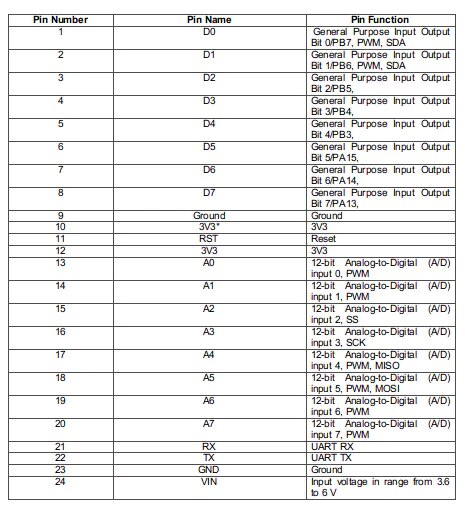
Pin Diagram

Pin Description
2. 16X2 Character LCD
The JHD162A LCD module has 16 pins and can be operated in 4-bit mode or 8-bit mode.

- Ground pin of the LCD module.
- Pin2(Vcc) ==> Power to LCD module (+5V supply is given to this pin)
- Pin3(VEE) ==> Contrast adjustment pin. This is done by connecting the ends of a 10K potentimeter to +5V and ground and then connecting the slider pin to the VEE pin. The voltage at the VEE pin defines the contrast. The normal setting is between 0.4 and 0.9V.
- Pin4(RS) ==> Register select pin.The JHD162A has two registers namely command register and data register. Logic HIGH at RS pin selects data register and logic LOW at RS pin selects command register. If we make the RS pin HIGH and feed an input to the data lines (DB0 to DB7), this input will be treated as data to display on LCD screen. If we make the RS pin LOW and feed an input to the data lines, then this will be treated as a command ( a command to be written to LCD controller – like positioning cursor or clear screen or scroll).
- Pin5(R/W) ==> Read/Write modes. This pin is used for selecting between read and write modes. Logic HIGH at this pin activates read mode and logic LOW at this pin activates write mode.
- Pin6(E) ==> This pin is meant for enabling the LCD module. A HIGH to LOW signal at this pin will enable the module.
- Pin7(DB0) to Pin14(DB7) ==> These are data pins. The commands and data are fed to the LCD module though these pins.
- Pin15(LED+) ==> Anode of the back light LED. When operated on 5V, a 560 ohm resistor should be connected in series to this pin. In arduino based projects the back light LED can be powered from the 3.3V source on the arduino board.
- Pin16(LED-) ==> Cathode of the back light LED.
3. LDR sensor(Photoresistor)
LDR or light dependent resistor is also known as photo resistor, photocell, photoconductor.It is a one type of resistor whose resistance varies depending on the amount of light falling on its surface. When the light falls on the resistor, then the resistance changes. These resistors are often used in many circuits where it is required to sense the presence of light. These resistors have a variety of functions and resistance. For instance, when the LDR is in darkness, then it can be used to turn ON a light or to turn OFF a light when it is in the light. A typical light dependent resistor has a resistance in the darkness of 1MOhm, and in the brightness a resistance of a couple of KOhm.
Working Principle of LDR
This resistor works on the principle of photo conductivity. It is nothing but, when the light falls on its surface, then the material conductivity reduces and also the electrons in the valence band of the device are excited to the conduction band. These photons in the incident light must have energy greater than the band gap of the semiconductor material.This makes the electrons to jump from the valence band to conduction.These devices depend on the light, when light falls on the LDR then the resistance decreases, and increases in the dark.When a LDR is kept in the dark place, its resistance is high and, when the LDR is kept in the light its resistance will decrease.
The LDR sensor is used to measure the incident light intensity. Light intensity is expressed in Lux. The sensor is connected to the A2 pin of Particle Photon. The sensor is connected in a potential divider circuit. The LDR provides an analog voltage which is converted to digital reading by the in-built ADC.

4.LM-35 Temperature sensor
LM35 is a precision IC temperature sensor with its output proportional to the temperature (in oC). The operating temperature range is from -55°C to 150°C. The output voltage varies by 10mV in response to every oC rise/fall in ambient temperature, i.e., its scale factor is 0.01V/ oC. The sensor has three pins - VCC, Analogout and Ground.

Features
- Calibrated directly in Degree Celsius (Centigrade)
- Linear at 10.0 mV/°C scale factor
- 0.5°C accuracy guarantee-able (at a25°C)
- Rated for full -55°C to a 150°C range
- Operates from 4 to 30 volts
- Less than 60 mA current drain
- Low self-heating, 0.08°C instill air
- Non-linearity only 0.25°C typical
- Low impedance output, 0.1Ωfor 1 mA load.
5.Solar Panel
Solar panels are devices that convert light into electricity. They got the name "solar" panels from the word 'Sol' used by astronomers to reference the sun and the sunlight. These are also called photovoltaic panels where Photovoltaic means "light-electricity". The phenomenon of converting the solar energy to electric energy is called photovoltaic effect. This effect generates the voltage and current at the output on the exposure of solar energy. A 3 Volts Solar panel is used in the project. A solar panel consists of several solar cell or photovoltaic diodes. These solar cells are P-N junction diode and they can generate an electric signal in presence of solar light. On exposure to the sunlight, this solar panel generates a DC voltage output of 3.3 V at its terminals. This panel can have maximum output power of 0.72 Watt and minimum output power of 0.6 Watt. Its maximum charging current is 220 mA and minimum charging current is 200 mA. The panel has two terminals - VCC and Ground. The voltage output is drawn from the VCC pin. The voltage output pin is connected to analog input pin A1 of the Particle Photon for measurement of the output power from the solar panel.
Software
Particle web IDE
For writing the program code for any Photon, developer needs to create an account on Particle website and register the Photon board with his user account. The program code then can be written on Web IDE at the Particle's website and transferred to a registered photon over the internet. If the selected Particle board, Photon here, is switched on and connected to cloud service of the Particle, the code is burnt to the selected board over the air via internet connection and the board starts operating according to the transferred code. For controlling board over the internet, a web page is designed which uses Ajax and Jquery to send data to the board using HTTP POST method. The web page identifies the board by a device ID and connects to the Particle's Cloud Service through an access token.
How to connect photon with Internet
1. Power your device
- Plug the USB cable into your power source.
- As soon as it is plugged in, the RGB LED on your device should begin blinking blue.If your device is not blinking blue, hold down the SETUP button.If your device is not blinking at all, or if the LED is burning a dull orange color, it may not be getting enough power. Try changing your power source or USB cable.
2. Connect your Photon to the Internet
There are two ways either you use web application or mobile app
a. Using web application
- Step 1 Go to setup.particle.io
- Step 2 Click on setup a Photon
- Step 3 After clicking on
NEXT, you should be presented with a file (photonsetup.html)
- Step 4 Open the file.
- Step 5 After opening the file connect your PC to the Photon, by connecting to the network named PHOTON.
- Step 6 Configure your Wi-Fi credentials.
Note :- If you mistyped your credentials, the Photon will blink dark blue or green. You have to go through the process again (by refreshing the page or clicking on the retry process part)
- Step 7 Rename your device. You will also see a confirmation if the device was claimed or not.
b. Using smartphone
- Open the app on your phone. Log in or sign up for an account with Particle if you don't have one.
- After login, press the plus icon and select the device you'd like to add. Then follow the instructions on the screen to connect your device to Wi-Fi.
If this is your Photon's first time connecting, it will blink purple for a few minutes as it downloads updates. It may take 6-12 minutes for the updates to complete, depending on your internet connection, with the Photon restarting a few times in the process.
Modes
- Cyan, your Photon is connected to the Internet.
- Magenta, it is currently loading an app or updating its firmware. This state is triggered by a firmware update or by flashing code from the Web IDE or Desktop IDE. You might see this mode when you connect your Photon to the cloud for the first time.
- Green, it is trying to connect to the internet.
- white, the Wi-Fi module is off.
Web IDE
Particle Build is an Integrated Development Environment, or IDE that means that you can do software development in an easy-to-use application, which just so happens to run in your web browser.
- To open build, login to your particle account and then click on build as shown in image.
- Once you clicked you will see console like this.

- To create a new create app, click on create new app.

- To include library in program, go to libraries section.

- And search for liquidcrystal.

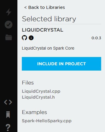
- Select an app in which you want to add library. In my case it is solarpanelmonitoring.

- To verify the program. Click on verify.

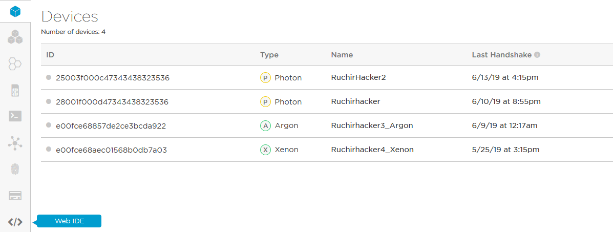
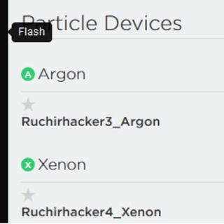
- To upload the code, click on flash but before doing that select a device.If you have more than one device you have to make sure that you have selected which of your devices to flash code to. Click on the "Devices" icon at the bottom left side of the navigation pane, then when you hover over device name the star will appear on the left. Click on it to set the device you had like to update (it won't be visible if you have only one device). Once you have selected a device, the star associated with it will turn yellow. (If you only have one device, there is no need to select it, you can continue.

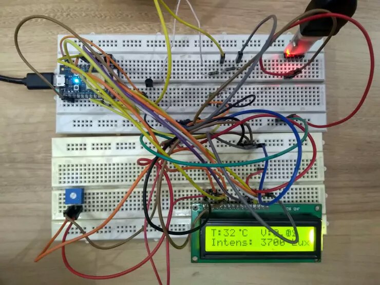
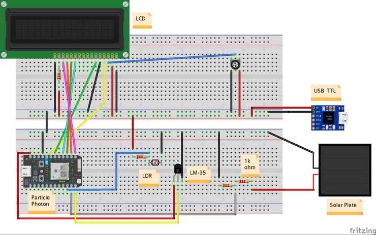
How the circuit works
In the circuit, 6 GPIO pins of the module are used to interface the character LCD and three analog input pins are used to interface LM-35 temperature sensor, Solar Panel and the LDR sensor.
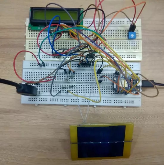
Once the circuit is assembled, it is ready to deploy along with the solar panel. While the solar panel keeps generating electricity, the attached to the device. The device is powered from the mains supply that is managing the other performance enhance equipment as well. Once the device is powered on, some initial messages are flashed on its LCD display indicating the intent of the application. The power output of the panel, temperature and the incident light intensity are measured by the Voltage Output pin of the solar panel, LM-35 temperature sensor and the LDR sensor respectively. The Voltage Output pin of the solar panel, LM-35 temperature sensor and the LDR sensor are connected to the analog input pins A1, A0 and A2 of the Particle Photon.
The respective parameters are measured by sensing the analog voltage at the respective pins. The analog voltage sensed at the respective pins is converted to digital values using in-built ADC channels. The Particle Photon has 12-bit ADC channels. So the digitized values can range from 0 to 4095. Here, it is assumed that the resistive network interfacing LDR sensor with the controller pin is calibrated to indicate light intensity by direct proportionality.
The LM-35 IC does not require any external calibration or trimming to provide typical accuracies of ±0.25 °C at room temperature and ±0.75 °C over temperature range from −55 °C to 150 °C. Under normal conditions, the temperature measured by the sensor won't exceed or recede the operational range of the sensor. Due to low-output impedance, linear output, and precise inherent calibration of the LM-35, the interfacing of the sensor to a control circuitry is easy. As the LM-35 device draws only 60 uA from the supply, it has very low self-heating of less than 0.1 °C in still air. Typically in the temperature range from −55 °C to 150 °C, the voltage output of the sensor increases by 10 mV per degree Celsius. The voltage output of the sensor is given by the following formula.
Vout = 10 mV/°C*T
where,
Vout = Voltage output of the sensor
T = Temperature in degree Celsius
                                                             T (in °C) = Vout/10 mV
                                                             T (in °C) = Vout(in V)*100
If VDD is assumed to be 3.3 V, the analog reading is related to the sensed voltage over 12-bit range by the following formula.
Vout = (3.3/4095)*Analog-Reading So, the temperature in degree Celsius can be given by the following formulae.
                                                             T (in °C) = Vout(in V)*100
                                                             T (in °C) = (3.3/4095)*Analog-Reading *100
The voltage output of the solar panel should be typically 3 V which can be directly sensed by the Particle Photon. The Particle photon can directly sense voltage up to 3.3 V. For digitization of the sensed analog voltage, it is again internally referenced to the VDD. The digitized voltage reading is scaled over the 12-bit range i.e. 0 to 4095.
Vout = (3.3/4095)*Analog-Reading
The sensor data is first displayed on the LCD display and then is passed to the Particle Cloud via Wi-Fi connection. The user needs to login into the Particle registered account in order to view the read sensor values. The platform allows connecting to a board from the registered account. The user can monitor received sensor data in real time and can also log data.
Connections
Photon ==> LCD
D6 ==> RS
D5 ==> Enable
D3 ==> DB4
D2 ==> DB5
D1 ==> DB6
D0 ==> DB7
Photon ==> LM-35
A0 ==> Aout
Photon ==> LDR
A2 ==> Vcc
Photon ==> Solar plate
A1 ==> Vcc
GND ==>GND
Note:- USB TTL is used to provide 5V to the LCD and LDR
Result

Top Comments