element14 Community
element14 Community
    Register Log In
  • Site
  • Search
  • Log In Register
  • About Us
  • Community Hub
    Community Hub
    • What's New on element14
    • Feedback and Support
    • Benefits of Membership
    • Personal Blogs
    • Members Area
    • Achievement Levels
  • Learn
    Learn
    • Ask an Expert
    • eBooks
    • element14 presents
    • Learning Center
    • Tech Spotlight
    • STEM Academy
    • Webinars, Training and Events
    • Learning Groups
  • Technologies
    Technologies
    • 3D Printing
    • FPGA
    • Industrial Automation
    • Internet of Things
    • Power & Energy
    • Sensors
    • Technology Groups
  • Challenges & Projects
    Challenges & Projects
    • Design Challenges
    • element14 presents Projects
    • Project14
    • Arduino Projects
    • Raspberry Pi Projects
    • Project Groups
  • Products
    Products
    • Arduino
    • Avnet Boards Community
    • Dev Tools
    • Manufacturers
    • Multicomp Pro
    • Product Groups
    • Raspberry Pi
    • RoadTests & Reviews
  • Store
    Store
    • Visit Your Store
    • Choose another store...
      • Europe
      •  Austria (German)
      •  Belgium (Dutch, French)
      •  Bulgaria (Bulgarian)
      •  Czech Republic (Czech)
      •  Denmark (Danish)
      •  Estonia (Estonian)
      •  Finland (Finnish)
      •  France (French)
      •  Germany (German)
      •  Hungary (Hungarian)
      •  Ireland
      •  Israel
      •  Italy (Italian)
      •  Latvia (Latvian)
      •  
      •  Lithuania (Lithuanian)
      •  Netherlands (Dutch)
      •  Norway (Norwegian)
      •  Poland (Polish)
      •  Portugal (Portuguese)
      •  Romania (Romanian)
      •  Russia (Russian)
      •  Slovakia (Slovak)
      •  Slovenia (Slovenian)
      •  Spain (Spanish)
      •  Sweden (Swedish)
      •  Switzerland(German, French)
      •  Turkey (Turkish)
      •  United Kingdom
      • Asia Pacific
      •  Australia
      •  China
      •  Hong Kong
      •  India
      •  Korea (Korean)
      •  Malaysia
      •  New Zealand
      •  Philippines
      •  Singapore
      •  Taiwan
      •  Thailand (Thai)
      • Americas
      •  Brazil (Portuguese)
      •  Canada
      •  Mexico (Spanish)
      •  United States
      Can't find the country/region you're looking for? Visit our export site or find a local distributor.
  • Translate
  • Profile
  • Settings
RF Radio Frequency
  • Challenges & Projects
  • Project14
  • RF Radio Frequency
  • More
  • Cancel
RF Radio Frequency
Blog Antenna Radiation - Phase 2
  • Blog
  • Forum
  • Documents
  • Events
  • Polls
  • Files
  • Members
  • Mentions
  • Sub-Groups
  • Tags
  • More
  • Cancel
  • New
Join RF Radio Frequency to participate - click to join for free!
  • Share
  • More
  • Cancel
Group Actions
  • Group RSS
  • More
  • Cancel
Engagement
  • Author Author: kmikemoo
  • Date Created: 4 Jan 2020 4:32 AM Date Created
  • Views 1779 views
  • Likes 7 likes
  • Comments 8 comments
  • rfradiofrequencych
  • ham radio
Related
Recommended

Antenna Radiation - Phase 2

kmikemoo
kmikemoo
4 Jan 2020
image

RF (Radio Frequency)

Enter Your Project for a chance to win a Spectrum Analyzer for the Most Innovative RF Project!

Back to The Project14 homepage image

Project14 Home
Monthly Themes
Monthly Theme Poll


Phase 2 of testing antenna radiation patterns.  The intro to this journey is Antenna Radiation.

Phase 2 will be to test a 3-element Yagi.  After measuring the 8 compass points (N, NE, E, SE, S, SW, W, NW), I will try to verify the shape of the forward lobe.


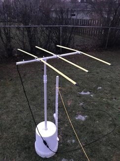
The original Yagi planned for this segment was a three-element one built into a re-purposed hockey stick.  But... that one was built for Radio Direction Finding and didn't have a means to mount it.  Once again, I had to move to Plan B - a tape measure Yagi.  I'm pretty sure that this one does not radiate directly off the end.  Moving forward, I will use the measurements to see if I can steer the beam more in line with what it should be,.

image

Preliminary testing of the tape measure Yagi showed enough promise to proceed but it does suffer from droopy elements and is very susceptible to wind moving the elements during testing.  As with the dipole test, the white stake under the radiating element is to insure that I make readings at the same distance from the feed point.

image

The graphic above is from Yagi-Uda.com and shows the operating characteristics of the three element "beam" antenna.


As we used to say in the Army... No plan ever survives contact with the enemy.  In one series of measurements, the main lobe cants left and a definite null shows in the rear right.  In another series, the main lobe cants right and there is a definite null in the rear left.  I will probably have to modify my tape measure Yagi to get repeatable measurements.


I have added PVC supports beneath each of the tape measure elements.  So much for being able to fold the elements for easy storage.  I videotaped another series of measurements.  This series somewhat agreed with the series from the day before.  It still doesn't seem correct.

image

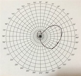
I had also taken a series of panoramic videos.  Using my measuring string and starting in the rear, I circled the antenna in a counterclockwise direction recording the meter output.  I reviewed those.  These resulted in something more like what I was expecting.

image

The rear lobes in the panoramic readings would be obscured by the center of the graph.  I attribute the low readings to having to overcome the P-N junction voltage of the Germanium diodes in the detector circuit of the meter.  When measured at 1 meter instead of two, the lobes are present but no where as clearly defined as the Yagi-Uda graphic above. At one meter, the rear lobe measured approximately 135mV.  The front lobe at the same distance was 2100mV.

The red arrow indicates the approximate center of the forward lobe and indicates less than bilateral symmetry.  Based on using this antenna for radio direction finding, this is correct.  I expected the skew to be greater, but that was probably corrected when I added the PVC support to the elements.


Testing the Yagi antenna proved to be challenging.  The originally flexible elements were most likely the culprits.  One cannot watch the meter AND the elements at the same time.


The second objective of this phase was to verify the shape of the forward lobe.  This exercise was underwhelming.  Step back slightly until the field strength meter reads approximately 200mV.  Drop a popsicle stick.  Yup.  It's an arc.


What was cool was seeing antenna polarization (orientation) in action.  It wasn't until the last series of measurements that it dawned on me to orient the field strength meter horizontally - since the Yagi is horizontally polarized as I have it mounted.  Readings that were in the 400mV range jumped up a full volt.  I had read that the wrong polarization results in a 20dB reduction.  During radio direction finding exercises (fox hunts), you want the attenuation to help localize the hidden transmitter.  I now have a means to demonstrate this concept to new radio amateurs.


Once the weather turns a bit nicer, I will try to trim the Yagi to get rid of the skew.  I will do this by measuring the RF power levels at 45 degrees right and 45 degrees left of center.  When they are as close as practical to one another, I will know that my forward lobe actually points forward.


Phase 3 will be to test an antenna with a cardioid radiation pattern.  Antenna Radiation - Phase 3

  • Sign in to reply

Top Comments

  • 14rhb
    14rhb over 5 years ago +4
    Hi Mike, Great results. I've found your blog very interesting and I hadn't heard of anyone using a retractable tape measure for Yagi elements before to enable it to be portable. It go me thinking (dangerous…
  • 14rhb
    14rhb over 5 years ago in reply to 14rhb +4
    Still got my thinking cap on ! You could maybe also repurpose the poles from an old sprung-fibreglass-pole tent? The couplings are often aluminium tube and the thin elastic is in the middle. If you could…
  • three-phase
    three-phase over 5 years ago +3
    This is a great project which I am enjoying following along with - keep up the good work! Kind regards
Parents
  • 14rhb
    14rhb over 5 years ago

    Hi Mike,


    Great results. I've found your blog very interesting and I hadn't heard of anyone using a retractable tape measure for Yagi elements before to enable it to be portable. It go me thinking (dangerous times now image). If you used some 20mm PVC conduit for the main support you could add in a 3/4-way box where the director, reflector or antenna elements are to be located. Gluing the main support pieces only. Use suitable stubs of 20mm conduit in the other port(s) of the 3/4-way but that can be pulled out for transportation. The tape measure is attached to the main support and loosely attached to the removable side pieces - perhaps a loose cable tie?

    image

    [Source: external CPC Farnell ]


    image

    • Cancel
    • Vote Up +4 Vote Down
    • Sign in to reply
    • More
    • Cancel
  • kmikemoo
    kmikemoo over 5 years ago in reply to 14rhb

    14rhb  Your post made me laugh at myself.  In my focus to get more consistent results, it never dawned on me to NOT glue the PVC supports in the fittings. Ha! Ha!  I really like the boxes you shared.  I would have to get them from Farnell as my local hardware store doesn't do metric (Wisconsin, USA).

    • Cancel
    • Vote Up +2 Vote Down
    • Sign in to reply
    • More
    • Cancel
  • 14rhb
    14rhb over 5 years ago in reply to kmikemoo

    Maybe you are too near to the action, but in a good way image.

    • Cancel
    • Vote Up 0 Vote Down
    • Sign in to reply
    • More
    • Cancel
Comment
  • 14rhb
    14rhb over 5 years ago in reply to kmikemoo

    Maybe you are too near to the action, but in a good way image.

    • Cancel
    • Vote Up 0 Vote Down
    • Sign in to reply
    • More
    • Cancel
Children
No Data
element14 Community

element14 is the first online community specifically for engineers. Connect with your peers and get expert answers to your questions.

  • Members
  • Learn
  • Technologies
  • Challenges & Projects
  • Products
  • Store
  • About Us
  • Feedback & Support
  • FAQs
  • Terms of Use
  • Privacy Policy
  • Legal and Copyright Notices
  • Sitemap
  • Cookies

An Avnet Company © 2025 Premier Farnell Limited. All Rights Reserved.

Premier Farnell Ltd, registered in England and Wales (no 00876412), registered office: Farnell House, Forge Lane, Leeds LS12 2NE.

ICP 备案号 10220084.

Follow element14

  • X
  • Facebook
  • linkedin
  • YouTube