


Thanks to Element14 community with all the swag gift and sincerely greeting.
I would be my pleasure to share my test project for the new due-core M33 product from NXP theming RF.
NFC Lock
1. Brief
The NFC tag reader works on 125kHz, if read tag via I2C match the authorized ID, the lock is opened until next detection loop.
The servo used in this project runs with 50Hz PWM frequency and dutycycle Percentage of 2.5% ~ 12.5%. In this design 5% vs 10% as On state and OFF state .
#define LOCK_ON 5
#define LOCK_OFF 10
Then update the PWM period for servo control.In which the last bit of rxBuff is set to 0xFF if the NFC ID is matched.g_master_rxBuff[I2C_DATA_LENGTH-1]g_dmvfvva g_master_rxBuff[I2C_DATA_LENGTH-1]ster_rxBuff[I2C_DATA_LENGTH-1]
updatedutyCyclePercent= LOCK_ON ? (g_master_rxBuff[I2C_DATA_LENGTH-1]==127):LOCK_OFF;
g_pulsePeriod = (g_pwmPeriod * (100 - updatedutyCyclePercent)) / 100;
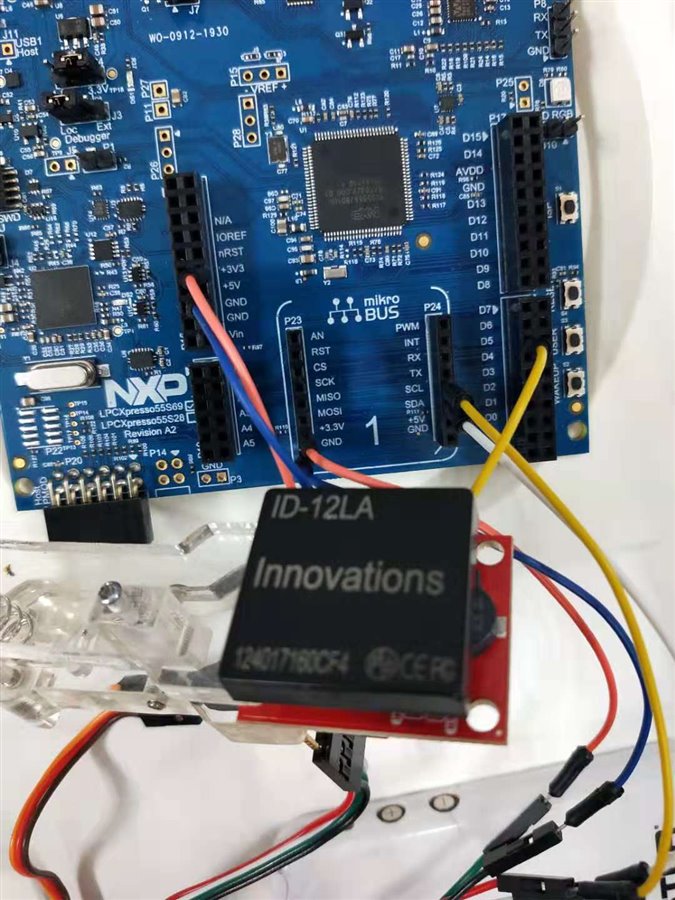
2. Hardware
2.1 LPC55S69 dev board
2.2 NFC tag reader ID-12LA, on 125kHz
3. Main Code
3.1 With I2C and ctimer PWM, the NFC lock can be coded as follows,
int main(void)
{
    i2c_master_config_t masterConfig;
    status_t reVal        = kStatus_Fail;
    uint8_t deviceAddress = 0x01U;

  ctimer_config_t config;
    uint32_t srcClock_Hz;
    uint32_t timerClock;
uint8_t updatedutyCyclePercent;


    /* attach 12 MHz clock to FLEXCOMM0 (debug console) */
    CLOCK_AttachClk(BOARD_DEBUG_UART_CLK_ATTACH);


    /* attach 12 MHz clock to FLEXCOMM8 (I2C master) */
    CLOCK_AttachClk(kFRO12M_to_FLEXCOMM4);


    /* Use 12 MHz clock for some of the Ctimers */
    CLOCK_AttachClk(kFRO_HF_to_CTIMER2);

    /* reset FLEXCOMM for I2C */
    RESET_PeripheralReset(kFC4_RST_SHIFT_RSTn);


    BOARD_InitPins();
    BOARD_BootClockPLL150M();
    BOARD_InitDebugConsole();

    /* CTimer0 counter uses the AHB clock, some CTimer1 modules use the Aysnc clock */
    srcClock_Hz = CTIMER_CLK_FREQ;


    PRINTF("CTimer example to generate a PWM signal\r\n");


    CTIMER_GetDefaultConfig(&config);
    timerClock = srcClock_Hz / (config.prescale + 1);


    CTIMER_Init(CTIMER, &config);


    /* Get the PWM period match value and pulse width match value of 50hz PWM signal with 2.5%~12.5% dutycycle , 20ms peoriod*/
    CTIMER_GetPwmPeriodValue(50, 10, timerClock);
    CTIMER_SetupPwmPeriod(CTIMER, CTIMER_MAT_OUT, g_pwmPeriod, g_pulsePeriod, false);
    CTIMER_StartTimer(CTIMER);
//CTIMER_UpdatePwmDutycycle(CTIMER_Type *base, ctimer_match_t matchChannel, uint8_t dutyCyclePercent);

    PRINTF("\r\nI2C board2board polling -- Master transfer.\r\n");


    g_master_txBuff[0] = I2C_DATA_LENGTH - 1U;
    for (uint32_t i = 1U; i < I2C_DATA_LENGTH; i++)
    {
        g_master_txBuff[i] = i - 1;
    }


    I2C_MasterGetDefaultConfig(&masterConfig);


    /* Change the default baudrate configuration */
    masterConfig.baudRate_Bps = I2C_BAUDRATE;


    /* Initialize the I2C master peripheral */
    I2C_MasterInit(EXAMPLE_I2C_MASTER, &masterConfig, I2C_MASTER_CLOCK_FREQUENCY);


    /* Wait until the slave is ready for transmit, wait time depend on user's case.
       Slave devices that need some time to process received byte or are not ready yet to
       send the next byte, can pull the clock low to signal to the master that it should wait.*/
    for (uint32_t i = 0U; i < WAIT_TIME; i++)
    {
        __NOP();
    }
    PRINTF("Receive sent data from slave :");

while (1)
    {
    for (uint32_t i = 0U; i < WAIT_TIME; i++)
    {        __NOP();    }
    /* Receive blocking data from slave */
    if (kStatus_Success == I2C_MasterStart(EXAMPLE_I2C_MASTER, I2C_MASTER_SLAVE_ADDR_7BIT, kI2C_Write))
    {


        reVal = I2C_MasterReadBlocking(EXAMPLE_I2C_MASTER, g_master_rxBuff, I2C_DATA_LENGTH - 1, kI2C_TransferDefaultFlag);
        if (reVal != kStatus_Success)
        {
            return -1;
        }


        reVal = I2C_MasterStop(EXAMPLE_I2C_MASTER);
        if (reVal != kStatus_Success)
        {
            return -1;
        }
    }


    for (uint32_t i = 0U; i < 4; i++)
    //for (uint32_t i = 0U; i < I2C_DATA_LENGTH - 1; i++)
    {
        if (i % 8 == 0)
        {
            PRINTF("\r\n");
        }
        PRINTF("0x%2x  ", g_master_rxBuff[i]);
if (g_master_rxBuff[i]== g_match_id[i] ){g_master_rxBuff[I2C_DATA_LENGTH-1]=127;}
    }
    PRINTF("\r\n\r\n");

// LOCK_UNLOCK, refreshed every loop and return to LOCK off status,
updatedutyCyclePercent= LOCK_ON ? (g_master_rxBuff[I2C_DATA_LENGTH-1]==127):LOCK_OFF;
g_pulsePeriod = (g_pwmPeriod * (100 - updatedutyCyclePercent)) / 100;
CTIMER_UpdatePwmDutycycle(CTIMER, CTIMER_MAT_OUT, g_pulsePeriod);


    }
    // PRINTF("\r\nEnd of I2C example .\r\n");
}
4. Demo video and pics.
| {gallery} NFC lock |
|---|
|
REPLACE THIS TEXT WITH YOUR IMAGE IMAGE TITLE: THEN IMAGE DESCRIPTION |
|
REPLACE THIS TEXT WITH YOUR IMAGE IMAGE TITLE: THEN IMAGE DESCRIPTION |
|
REPLACE THIS TEXT WITH YOUR IMAGE IMAGE TITLE: THEN IMAGE DESCRIPTION |
|
REPLACE THIS TEXT WITH YOUR IMAGE IMAGE TITLE: THEN IMAGE DESCRIPTION |


And the demo video
Top Comments