 | Enter Your Electronics & Design Project for Your Chance to Win a $100 Shopping Cart! | Project14 Home |
| Monthly Themes | ||
| Monthly Theme Poll |
As an alternative to working on RoboBobLet for the Robots on Wheels challenge I decided to make a new mobile robot for a children's club called Messy Church that I am involved with. They wanted a marble tilt maze game but this seemed a bit dull so I decided to make it a mobile robot tilt maze game instead. I already had a suitable mobile robot chassis in the form of a BigTrak Ranger. These are designed to use a smart phone to control them. For RoboBobLet I am planning to use a BNO055 9 DOF IMU sensor to try and track the movements of RoboBobLet and I needed some experience with using this sensor so it seemed a good match to use it with the BigTrak Ranger to make the robot tilt maze game.
The BigTrak Ranger is designed to have a smart phone inserted into the slot and then connected to a laptop via Bluetooth to enable it to be controlled manually. I wasn't interested in the existing control method as I wanted to add my own Arduino Nano based version. The BigTrak Ranger uses opto-sensors to transfer control information from the smart phone to the on-board electronics. It seemed reasonable that I should be able to just replace the smart phone with four LEDs controlled by the Nano. Unfortunately it didn't turn out to be as simple as this as once the rear clip which was designed to hold the smart phone in place was removed, there was just too much light entering the system and the LEDs did not have any impact.
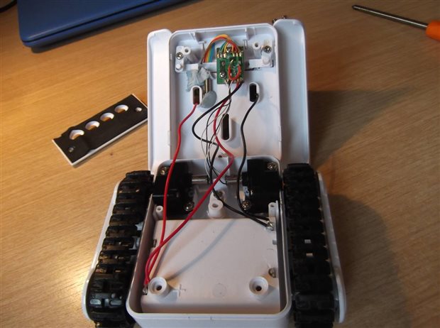
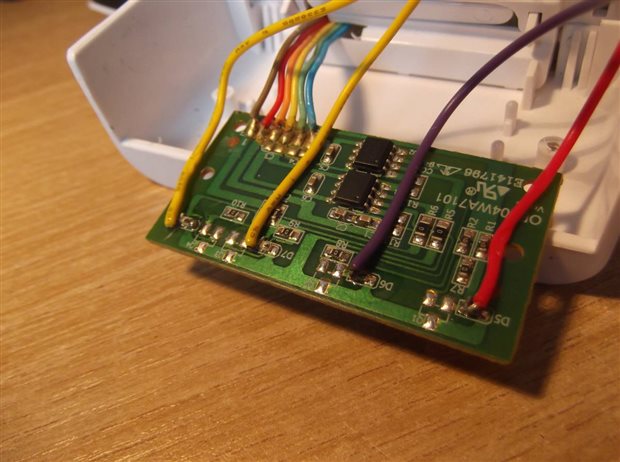
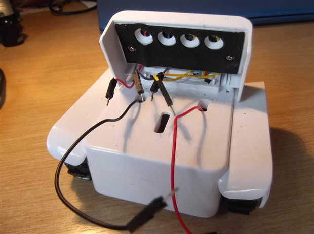
So, I decided to take the system apart to see if there was another way. There are three small screws on the bottom - two of which are in the battery compartment (one of which is unhelpfully located behind a battery spring). This enables the rear part of the smart phone holder to be removed leaving space for the protoboard and Nano. The motors used are the small ones typically used in tooth brushes, so not that powerful but OK. A small gear box is used to increase the torque, but this does reduce the speed. There is a small micro-switch ON/OFF power switch on a PCB, with the main electronics contained on a second PCB mounted on the front holder for the smart phone. This essentially contains four optical sensors, probably opto-diodes but they could be opto-transistors, as well as two what I think are single channel H bridge drivers (one for each motor). I did think initially that I might have to cut into the PCB tracks connected to the H bridge drivers but after looking at the optical-sensors I decided to try just soldering on wires between the sensors and the load resistor. The opto-sensors produce a 0V signal when exposed to light at this point so I reasoned that if I connected a wire to a Nano output I might be able to over-ride the sensor. There could have been a problem if a small load resistance was being used as this would then effectively almost short-circuit the power supply. However, most optical sensors have a larger load resistance which would not be a problem so I thought it was worth a chance. All I then did was to solder four wires, one to each of the opto-sensors bringing them out to the top of the BigTrak Ranger chassis so that they could be plugged into the proto-board. One opto-sensor controls left track forwards, another controls left track backwards, with the other two controlling the right track. A bit of an odd way of controlling the two tracks but it means only simple on-off optical signals need to be used. (I didn't experiment with turning both left-track forwards and left-track backwards on at the same time as it may well short the power supply. I also brought out power wires which I soldered to the battery holder. This does mean that there isn't an on-off switch so I have to remember to remove a battery when I am no longer using it. This seems to work OK.
As I wanted the system to operate autonomously in some way I decided to add a BNO055 9 DOF IMU from Adafruit. The default programme provided with this device extracts the information from the IMU as (X, Y, Z) values. The system fitted in nicely with Z representing the tilt forwards (and backwards) and Y the tilt sideways (left or right). I then amended the default programme to use the Z axis to control forward motion and the Y axis to implement a turn sideways so that the vehicle would move to always be pointing downhill. The result is that the mobile robot can be controlled to move about by simply lifting the surface at the appropriate angle. It creates a sort of marble tilt maze game but using the robot instead of a marble.
The video below shows the system in operation. I made a maze by Bluetacking some children's wooden bricks to a larger piece of flat MDF. The children loved it and it stayed operational for the entire club, which was a relief.
Now, it is back to RoboBobLet to see how the BNO055 might be used to determine it's location and movement. Or maybe the camera, I cannot decide, as time is beginning to run out.


Top Comments
-

genebren
-
Cancel
-
Vote Up
+1
Vote Down
-
-
Sign in to reply
-
More
-
Cancel
Comment-

genebren
-
Cancel
-
Vote Up
+1
Vote Down
-
-
Sign in to reply
-
More
-
Cancel
Children