element14 Community
element14 Community
    Register Log In
  • Site
  • Search
  • Log In Register
  • About Us
  • Community Hub
    Community Hub
    • What's New on element14
    • Feedback and Support
    • Benefits of Membership
    • Personal Blogs
    • Members Area
    • Achievement Levels
  • Learn
    Learn
    • Ask an Expert
    • eBooks
    • element14 presents
    • Learning Center
    • Tech Spotlight
    • STEM Academy
    • Webinars, Training and Events
    • Learning Groups
  • Technologies
    Technologies
    • 3D Printing
    • FPGA
    • Industrial Automation
    • Internet of Things
    • Power & Energy
    • Sensors
    • Technology Groups
  • Challenges & Projects
    Challenges & Projects
    • Design Challenges
    • element14 presents Projects
    • Project14
    • Arduino Projects
    • Raspberry Pi Projects
    • Project Groups
  • Products
    Products
    • Arduino
    • Avnet Boards Community
    • Dev Tools
    • Manufacturers
    • Multicomp Pro
    • Product Groups
    • Raspberry Pi
    • RoadTests & Reviews
  • Store
    Store
    • Visit Your Store
    • Choose another store...
      • Europe
      •  Austria (German)
      •  Belgium (Dutch, French)
      •  Bulgaria (Bulgarian)
      •  Czech Republic (Czech)
      •  Denmark (Danish)
      •  Estonia (Estonian)
      •  Finland (Finnish)
      •  France (French)
      •  Germany (German)
      •  Hungary (Hungarian)
      •  Ireland
      •  Israel
      •  Italy (Italian)
      •  Latvia (Latvian)
      •  
      •  Lithuania (Lithuanian)
      •  Netherlands (Dutch)
      •  Norway (Norwegian)
      •  Poland (Polish)
      •  Portugal (Portuguese)
      •  Romania (Romanian)
      •  Russia (Russian)
      •  Slovakia (Slovak)
      •  Slovenia (Slovenian)
      •  Spain (Spanish)
      •  Sweden (Swedish)
      •  Switzerland(German, French)
      •  Turkey (Turkish)
      •  United Kingdom
      • Asia Pacific
      •  Australia
      •  China
      •  Hong Kong
      •  India
      •  Korea (Korean)
      •  Malaysia
      •  New Zealand
      •  Philippines
      •  Singapore
      •  Taiwan
      •  Thailand (Thai)
      • Americas
      •  Brazil (Portuguese)
      •  Canada
      •  Mexico (Spanish)
      •  United States
      Can't find the country/region you're looking for? Visit our export site or find a local distributor.
  • Translate
  • Profile
  • Settings
Sensors Projects
  • Challenges & Projects
  • Project14
  • Sensors Projects
  • More
  • Cancel
Sensors Projects
Blog Hall sensor AS5600 for Game Wheel.
  • Blog
  • Forum
  • Documents
  • Events
  • Polls
  • Files
  • Members
  • Mentions
  • Sub-Groups
  • Tags
  • More
  • Cancel
  • New
Join Sensors Projects to participate - click to join for free!
  • Share
  • More
  • Cancel
Group Actions
  • Group RSS
  • More
  • Cancel
Engagement
  • Author Author: maxpowerr
  • Date Created: 15 Nov 2020 12:55 PM Date Created
  • Views 22994 views
  • Likes 9 likes
  • Comments 6 comments
  • sensorsch
Related
Recommended

Hall sensor AS5600 for Game Wheel.

maxpowerr
maxpowerr
15 Nov 2020
image

Sensors

Enter Your Electronics & Design Project for a chance to win a $200 shopping cart!

Submit an EntrySubmit an Entry  Back to homepage image
Project14 Home
Monthly Themes
Monthly Theme Poll


     Introduction.

image

     It was interesting for me to try using a hall sensor to determine the steering angle and try it in the game.


     Description AS5600. (Description taken from datasheet.)

imageimage

     The AS5600 is an easy to program magnetic rotary position sensor with a high-resolution 12-bit analog or PWM output. This contactless system measures the absolute angle of a diametric magnetized on-axis magnet. This AS5600 is designed for contactless potentiometer applications and its robust design eliminates the influence of any homogenous external stray magnetic fields. The industry-standard I²C interface supports simple user programming of non-volatile parameters without requiring a dedicated programmer. An easy start and stop position programming in a so called “3 wire mode” without a programmer or digital interface is also implemented. The default range of the output is 0 to 360 degrees. The AS5600 can be applied to smaller range by programming a zero angle (start position) and a maximum angle (stop position). The AS5600 is also equipped with a smart low power mode feature to automatically reduce the power consumption.


     This microcircuit contains four Hall sensors arranged in a circle. The internal Hall elements are placed in the center of the package on a circle with a radius of 1 mm.

image


     The typical airgap is between 0.5 mm and 3 mm, and it depends on the selected magnet. A larger and stronger magnet allows a larger airgap. Using the AGC value as a guide, the optimal airgap can be found by adjusting the distance between the magnet and the AS5600 so that the AGC value is in the center of its range. The maximum allowed displacement of the rotational axis of the reference magnet from the center of the package is 0.25 mm when using a magnet with a diameter of 6mm.

image


     The AS5600 allows controlling the direction of the magnet rotation with the DIR pin. If DIR is connected to GND (DIR = 0) a clockwise rotation viewed from the top will generate an increment of the calculated angle. If the DIR pin is connected to VDD (DIR = 1) an increment of the calculated angle will happen with counterclockwise rotation.
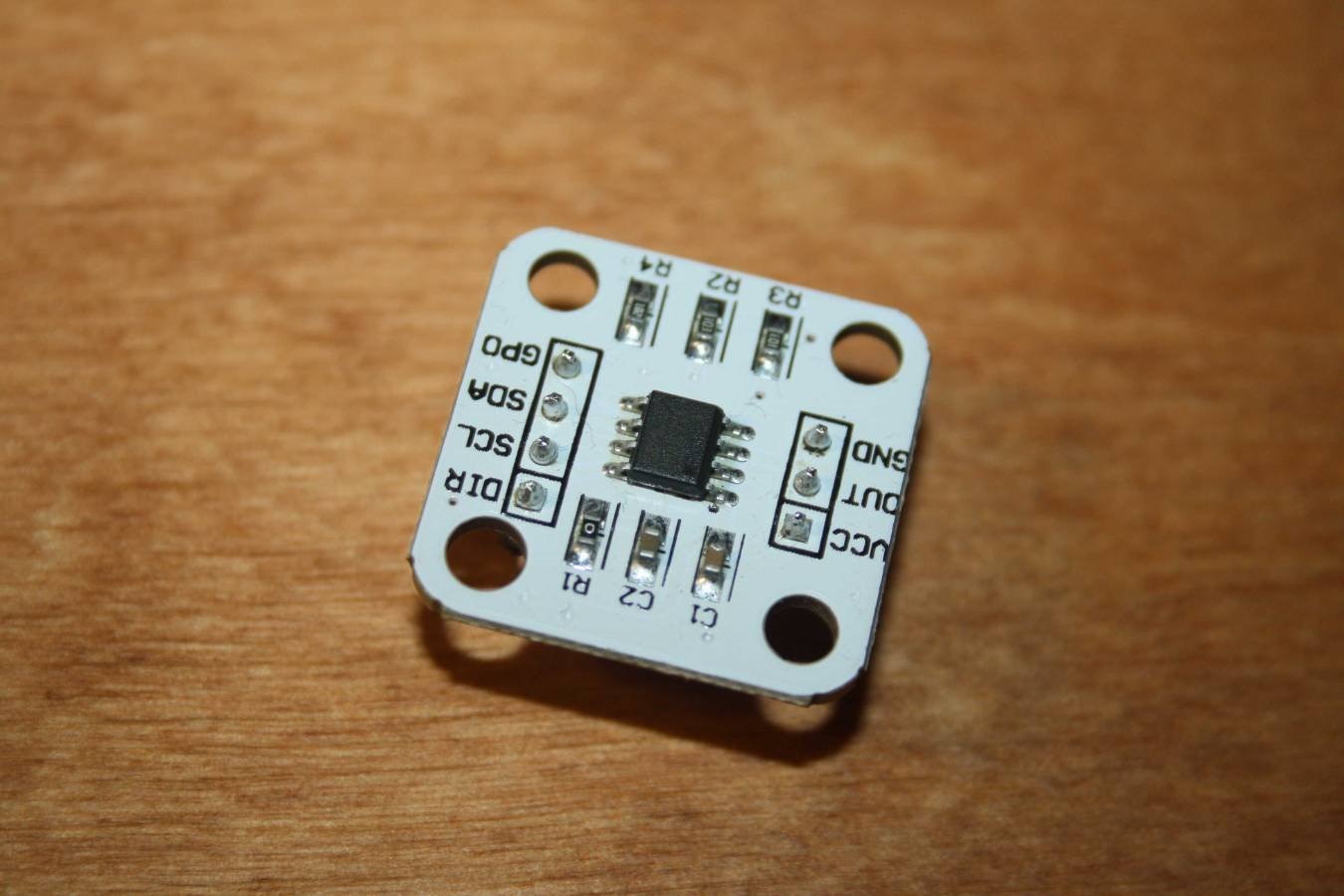

image


     Arduino module.

               image


Pin Description
Vcc

3.3V

GND

Power Ground

OUT

PWM /Analog voltage output

DIR

Rotational direction (ground=Value increases clockwise; thenVCC =Clockwise values are decreased)

SCL

The communication clock line

SDA

Data communication line

GPO

Mode selection (internal pull ground=Programming mode)


     Connecting to Arduino.

     In order for Arduino to be defined as a joystick in Windows, you need to use Arduino Pro Micro or Leonardo.


Connection diagram:


AS5600 Module Pin Arduino Pro Micro 3v3 Pin
Vcc Vcc
GND GND
DIR GND
SCL 3
SDA 2

The DIR pin must be connected to ground in order for the values to increase clockwise.


     For this module, I took a diametrical magnet. The picture below shows how the poles of the magnet are located.

image


      You can identify them by how they are magnetised. They should magnetically sideways to each other.

image


     I also printed a small case and a magnet holder.

imageimage

image


     Code.

     You will need to download two libraries. AS5600.h for working with the module and Joystick.h for Arduino to be defined as a game device (Links will be at the end of the article.)


#include <AS5600.h>
#include <Joystick.h>

AS5600 encoder;

Joystick_ Joystick(JOYSTICK_DEFAULT_REPORT_ID, 
  JOYSTICK_TYPE_MULTI_AXIS, 4, 0,
  false, false, false, false, false, false,
  false, false, true, true, true);

int Wheel;

void setup() {

// Initialize Joystick Library
  Joystick.begin();
  Joystick.setSteeringRange(0, 4059);

}

void loop() {

  Wheel = encoder.getPosition();

  // Output Controls
  Joystick.setSteering(Wheel);
  Joystick.sendState();

}


   Running.

     After you upload the firmware, the Arduino will be detected as a game device. To check this press the key combination Win + r.

image

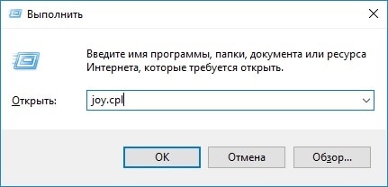
And enter the command joy.cpl.


     A menu of game devices will open.

image

The list will show an Arduino with an OK status.

Click the properties item and you will see the game device check menu. Where you can see the rudder axis movement.

image

Now you can start the game and try.

You don't have permission to edit metadata of this video.
Edit media
x
image
Upload Preview
image


Links:

Library for AS5600 module: https://github.com/kanestoboi/AS5600

Joystick Library: https://github.com/MHeironimus/ArduinoJoystickLibrary

3D Model: https://www.thingiverse.com/thing:4656550

Datasheet AS5600: https://ams.com/documents/20143/36005/AS5600_DS000365_5-00.pdf/649ee61c-8f9a-20df-9e10-43173a3eb323

  • Sign in to reply

Top Comments

  • DAB
    DAB over 4 years ago +2
    Nice build. DAB
  • dubbie
    dubbie over 4 years ago +2
    I like this device as I have always wanted to know more about Hall sensors and this type of project is something that is interesting to me as it could be used in mobile robots, especially for outdoor mobile…
  • maxpowerr
    maxpowerr over 4 years ago in reply to dubbie +2
    Thank you for your comment. I added a link to the STL file and Datasheet to the article. I have also added additional descriptions. I used a diametrical magnet with a diameter of 6 mm and a thickness of…
  • maxpowerr
    maxpowerr over 2 years ago in reply to Chandu070

    Here is the link https://aliexpress.ru/item/4001240626350.html?sku_id=10000015425282925&spm=a2g2w.productlist.search_results.1.72704aa63eZNOi on Aliexpress where you can buy this board. I printed the magnet holder on a 3D printer. A link to the 3D model is at the end of the article.

    • Cancel
    • Vote Up 0 Vote Down
    • Sign in to reply
    • More
    • Cancel
  • Chandu070
    Chandu070 over 2 years ago

    Hey maxpowerr 

    could you provide me the link to the product used above product(small case and an Orange magnet holder)

    Thank you in Advance,

    • Cancel
    • Vote Up 0 Vote Down
    • Sign in to reply
    • More
    • Cancel
  • dubbie
    dubbie over 4 years ago in reply to maxpowerr

    Thanks for that. I'll look up the details. Not sure what a diametrical magnet is so I'll have to look up that as well.


    Dubbie

    • Cancel
    • Vote Up +1 Vote Down
    • Sign in to reply
    • More
    • Cancel
  • maxpowerr
    maxpowerr over 4 years ago in reply to dubbie

    Thank you for your comment.

    I added a link to the STL file and Datasheet to the article. I have also added additional descriptions. I used a diametrical magnet with a diameter of 6 mm and a thickness of 2.5 mm. The magnet is inserted into the wheel and rotates in place with it. The distance from the chip to the magnet was approximately 1.3mm. This microcircuit seemed to me optimal in terms of price and performance, besides, it is sold in a ready-made module.

    There are also interesting similar chips TLE5011 / TLE5010 and KMZ41.

    • Cancel
    • Vote Up +2 Vote Down
    • Sign in to reply
    • More
    • Cancel
  • dubbie
    dubbie over 4 years ago

    I like this device as I have always wanted to know more about Hall sensors and this type of project is something that is interesting to me as it could be used in mobile robots, especially for outdoor mobile robots where being able to seal the body of the robot to protect against weather is a good idea.


    I looked up the device and it seems to be wildly variable in pricing from suitably cheap to way to much money. I have selected a couple of the suitably cheap ones, hopefully they will be OK. Would you be able to provide the STL files for the 3D printing - I could make my own but it probably wouldn't be as good as yours. Also, it isn't clear to be, does the magnet fit into the top wheel part and rotate above the sensor? Is it some kind of special magnet?


    A good project.


    Dubbie

    • Cancel
    • Vote Up +2 Vote Down
    • Sign in to reply
    • More
    • Cancel
>
element14 Community

element14 is the first online community specifically for engineers. Connect with your peers and get expert answers to your questions.

  • Members
  • Learn
  • Technologies
  • Challenges & Projects
  • Products
  • Store
  • About Us
  • Feedback & Support
  • FAQs
  • Terms of Use
  • Privacy Policy
  • Legal and Copyright Notices
  • Sitemap
  • Cookies

An Avnet Company © 2025 Premier Farnell Limited. All Rights Reserved.

Premier Farnell Ltd, registered in England and Wales (no 00876412), registered office: Farnell House, Forge Lane, Leeds LS12 2NE.

ICP 备案号 10220084.

Follow element14

  • X
  • Facebook
  • linkedin
  • YouTube