 | Monthly project competitions, chances to earn prizes, you decide project themes, your ideas, your projects, turn ideas into projects. | Project14 Home |
| Monthly Themes | ||
| Monthly Theme Poll |
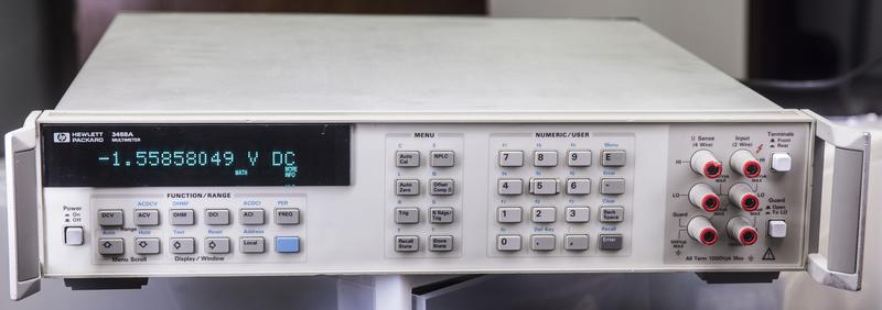
3458A. People who are into precision gear, need no introduction.
I wanted one since long ago, but not having business need in it, was not worth buying, as these even used on secondary market are going for good 3000-5000$ USD. But when I saw one dead unit for 750$, I could not resist and bite it. Seller photos were quite scary, with rust all over steel frame, but PCB boards looked "okay", so I hope for the best.
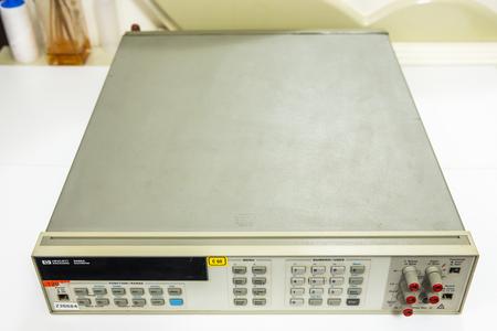
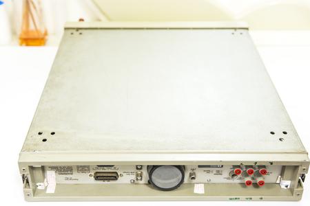
After some good money for shipping (beast is 15kg weight and size of average 2U rackmount server), I got it and did initial inspection:
* U100 processor MC68HC000P8 had paper sticker BAD (A5 board manufactured 1990)
* Missing button cap and lever for on power switch, guard switch and front/rear switch.
* Missing fuse binding post for amps on front panel
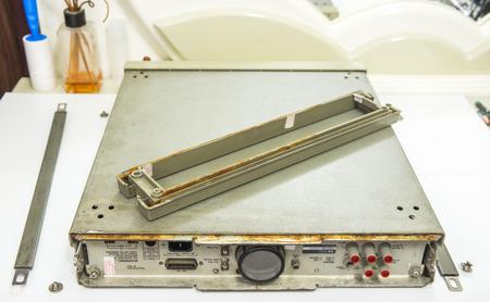
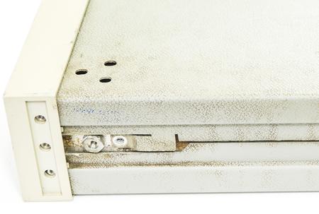
* Rust on steel chassis
* Mark "X" on mains power transformer
* Mark "X" on analog DC board 66501 (manufactured 1996)
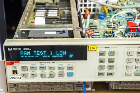
* Error message RAM 1 LOW
* Missing voltage reference board (so calibration is meaningless, even if it's still intact in 1990 year DS1220)..
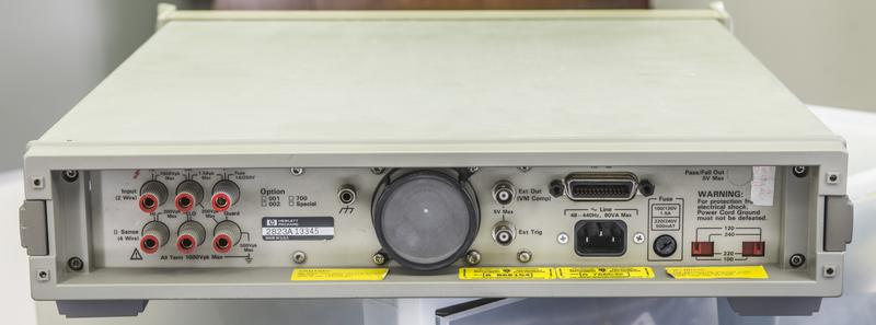
* Missing fuse holder for mains
* Damaged plastic rear panel
* No legs
* Dead fan
* Likely dead NVRAMs and lost cal as they are way too old.
Smell like lots of work, lots of debug folks.
Let's see what we are dealing with..
Always sad to see such instrument in mistreated condition. 3458A is current model, and you can get brand new one from Keysight, if you ready to fork 9.5K$, in base configuration.
Let's see what's inside..
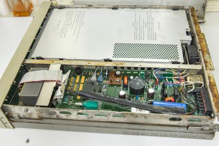
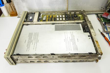
Cover's removed:
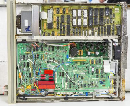
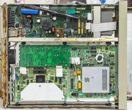
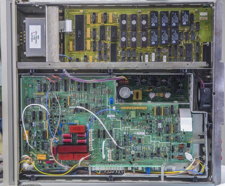
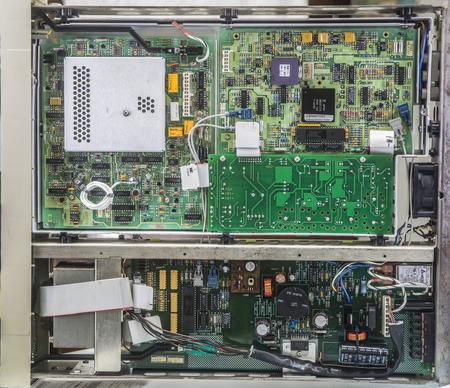
View on both sides without covers. As we can see, no A9 voltage reference with Linear LTZ1000 present. New A9 reference module from Keysight runs for 700$, but hey, I don't need go that way. I had own LTZ1000(A) based references, on which I spent multiple hundreds, and on second source there is eBay, where these references popup for sale like mushrooms after rain. I snagged one of those already , should arrive somewhen next week. So we covered here..
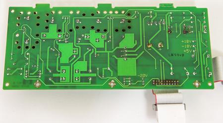
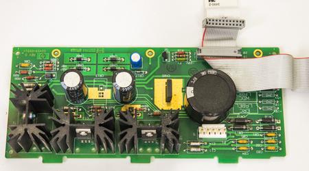
Inguard PSU. Some PCB damage around CR12 visible.
Outguard primary PSU. All seems ok, but need cleaning..
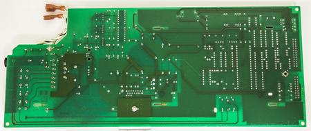
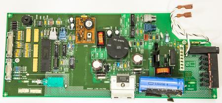
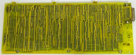
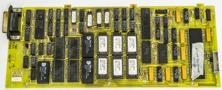
68000 CPU, RAM, ROM and digital logic, board A5. Dated 1990, while rest of analog PCBs dated 1996.
Probably seller changed digital PCB afterwards?
Removing inguard PSU for now, adding jumpwire instead of fuse (don't have suitable cap), turning on...
It's works!.. Well, not really  Analog side completely disconnected and unpowered at this moment, just check digital and power sections first.
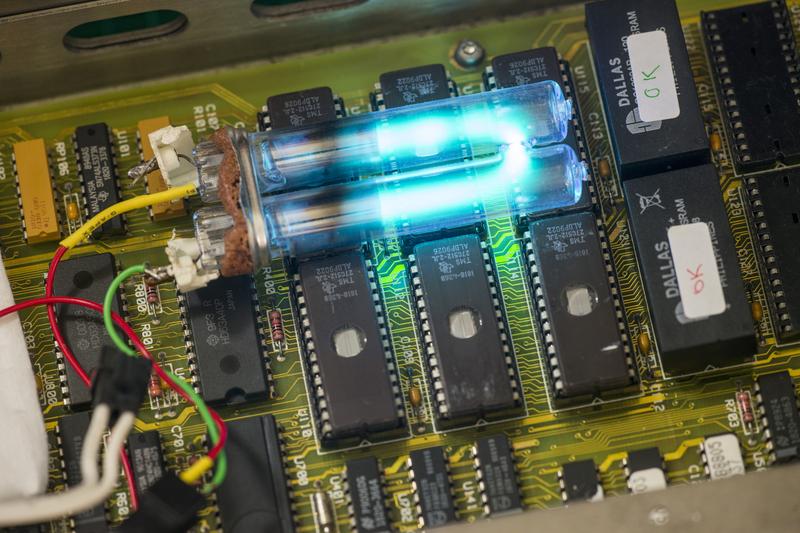
Nice and bright VFD, which is good, as it's hard to get replacement for those.
Now will remove Dallas NVRAMs , and solder sockets instead, so we can troubleshoot this RAM 1 LOW.
Front panel must be removed in order to remove mains transformer.
Looking good, just minor cleaning required..
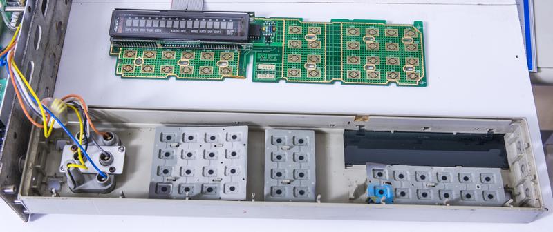
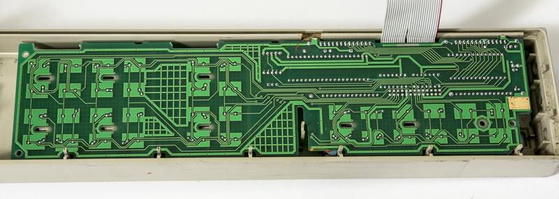
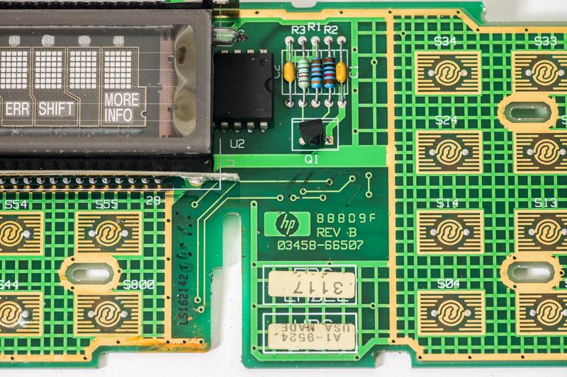
Frontpanel PCBA label and front binding post terminals.
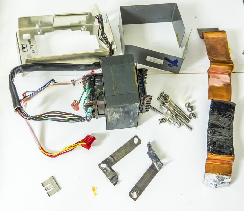
Now, we can take transformer out. I tried to open it up, but it's all covered in lacquer, and my patience run out quickly after wasting a hour trying to take it apart.
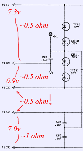
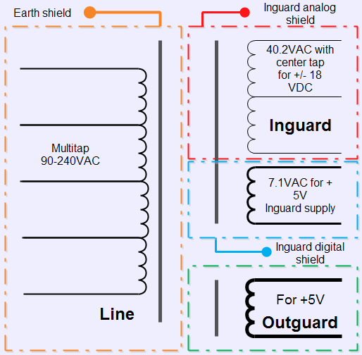
Transformer have two winding sections, primary with secondary for outguard +5V rail (goes to digital board and front panel, that's why it's working).
Second section for inguard supply is inner bobin with two secondary windings (one with center tap to generate +18/-18 and second for +5V analog).
This windings in my transformer are shorted together!
I would not trust repaired/rewinded transformer in such an instrument anyway, so going to make Agisight richer for $337 to get new transformer.
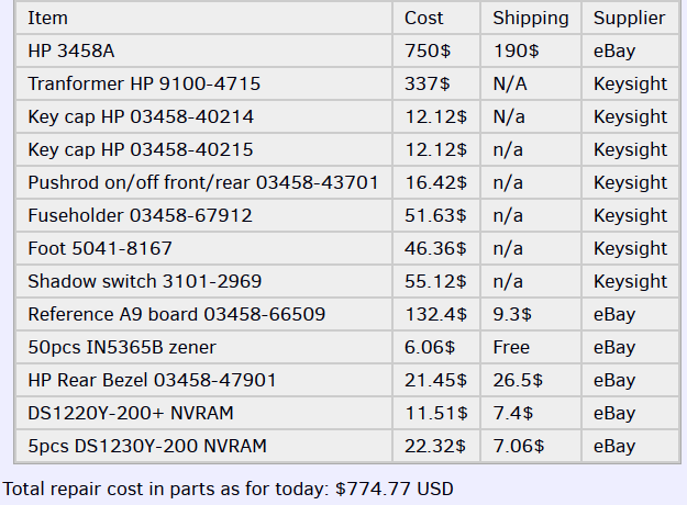
In case someone got FALSE impression that buying dead HP 3458A and fixing it would be cheap way to get yourself 8.5-digit DMM, think again.
Here are expenses on my unit already so far:
Add calibration (let's say you go full tilt, standard's grade cal $2660), and you looking into healthy 4.4K$, for which you can get working and likely even calibrated 3458A from second-market, if you patient and shake trees good enough.
Also you can see I cut few corners here and there with parts from eBay, as if you go with all original parts from Keysight, it will be much more (Reference board alone is 700$, like mentioned before).
Since I wait for new transformer to arrive, how can we test inguard supply to confirm it's OK?
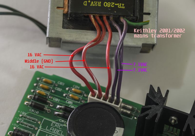
I have a "solution". From previous Keithley Model 2001 repair projects I have one extra power transformer, which happen to have same voltage outputs, as HP one, just at lower power rating. But since we connect only inguard supply A4 board, we don't need full power to check LDO's operation. So let's replace blown zeners and test A4 PCBA with properly wired Keithley mains TR-280 transformer. Never know which parts could ever come handy, eh?
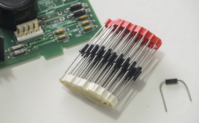
But first, replaced original CR11,CR12 with fresh zeners (got 50pcs from eBay, just few dollars with free shipping).
Cleaned board both sides, everything else look intact and good.
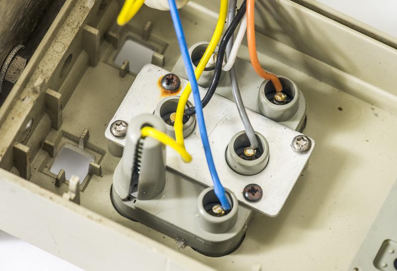
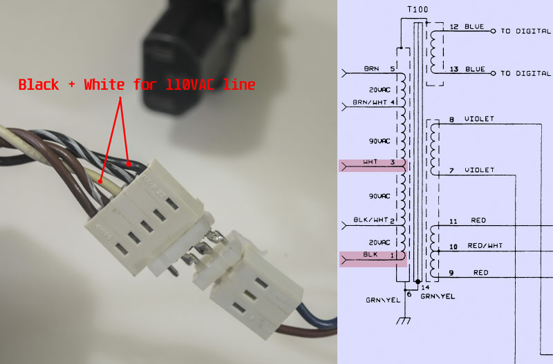
Now can connect input IEC plug socket to transformer's primary (since I need 110VAC, I used WHITE + BLACK wires).
Keithley used same type of 5-pin connector, but with different pinout. Secondary connector need rewiring as on photo above. I powered transformer separately and measured VAC voltages on secondary, without A4 board connected, to make sure all voltages correct.
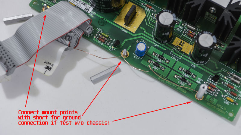
If you see schematics of A4 board in 3458A Multimeter Component Level Repair Manual, you may noticed MH1,MH2,MH3 connections. These are connected directly to guard frame in 3458A's chassis, which is acting as mecca star point for GND potential. Since I testing board separately, not mounted to chassis, I needed to connect these MH* points together with copper wire. This will be our ground point for measurements as well.
Apply power to transformer, and if nothing smokes, test output DC voltage.
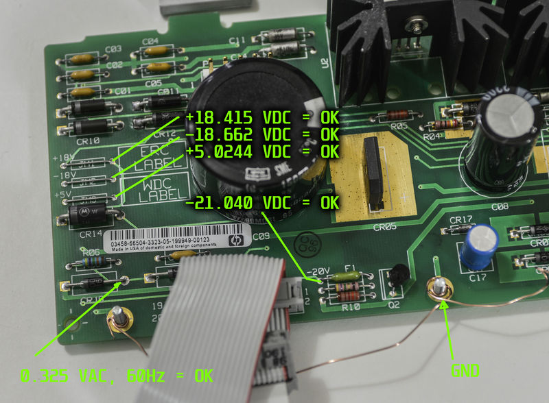
There are nice labels near test points, telling us voltage test points location.
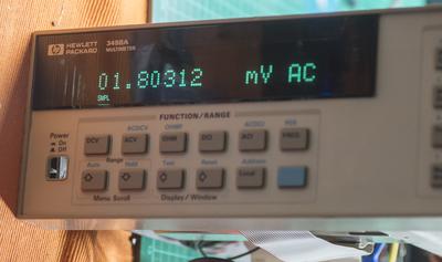
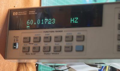
All voltages are OK, also 0.325VAC 60Hz signal to read mains frequency is OK too.
Repair of A4 inguard power supply now complete.
I also got used bezel off eBay in good condition, to save some money on this project, as it's just mechanical part to keep meter in one piece.
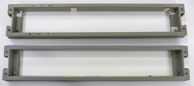
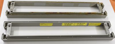
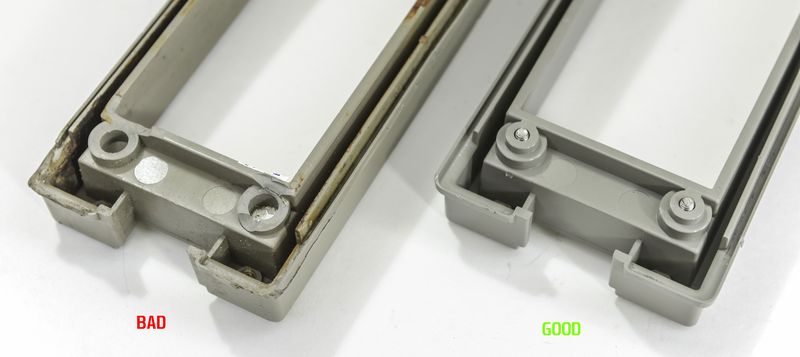
New one on bottom side, old busted rear bezel is on top.
Original unit's bezel had three out of four screw mounts destroyed, so it was not holding well.
Stay tuned, to be continued... 
Nice detailed article. Thanks! 
Made an order on Digikey for fan, caps to recap A6 outguard power supply board (can call me paranoid, but I don't trust 20 year old electrolyte capacitors.). 
Only gotcha is that there was no axial type C8 8300uF 35V capacitor, so I got usual one of similar size instead, will bodge something up. 
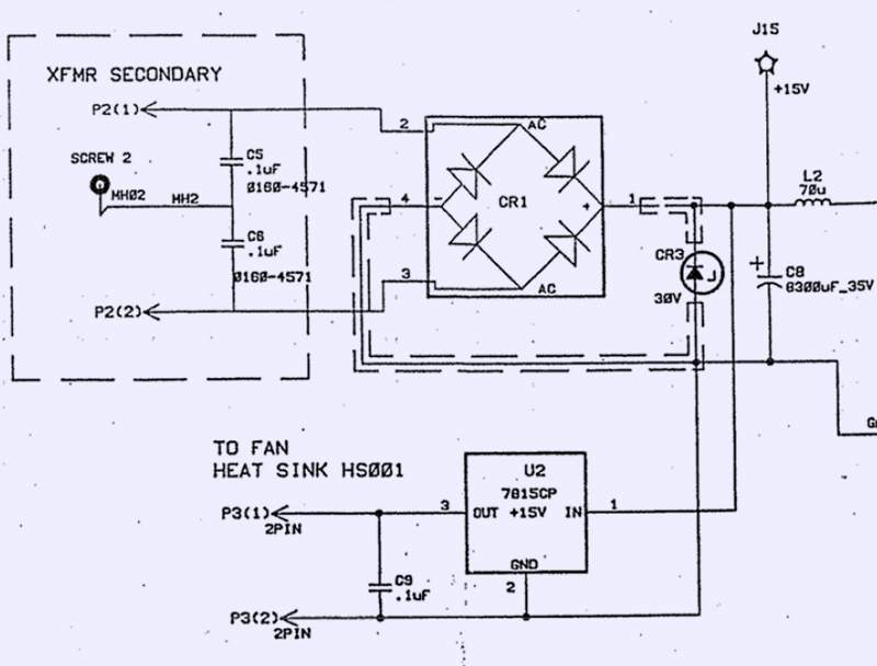
See anything suspicious?
Hint-hint : P3 connector goes directly to fan... 
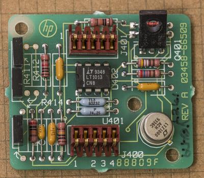
Missing board A9 arrived yesterday, now we have an 8ppm/year voltage reference!
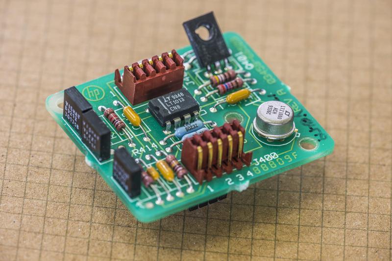
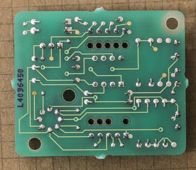
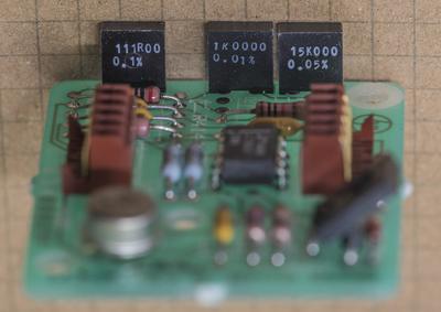
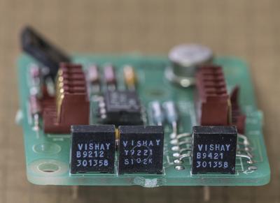
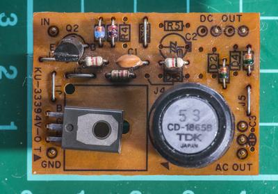
PCBA shots:
Vishay foil Resistors look
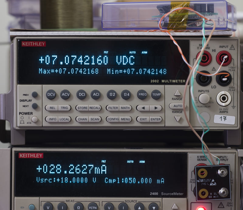
And quick check if it's working correctly, with Keithley 2002 as measuring DMM and Keithley 2400 as power source.
About +7.07421 VDC @26.5°C ambient. My 2002 is few ~30ppm's low compared to 2001 Cal.
One good thing about used references, they likely to be nicely aged. LTZ1000A on this one is made in 1993, in case someone miss it.
Only better with time.
Hi Illya,
I really enjoyed following your repair process. Great pictures and explanations.
John
Alright, here's next update, for those who follow 
A5 board
Replaced original rusty GPIB connector with fresh one from dead 33120A PCB, I had around.
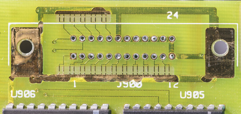
Funny traces are PCB spark-gaps for some ESD protection on interface. Never see such on interfaces ports before, but it's more common on mains SMPS units.
IPA+water bath for board to clean 25-year old dirt.
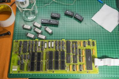
Now since monday I will have my Digikey package with new caps, I removed old ones. They looked alright, so most of you guys would think - hey, those caps probably okay, don't waste your time?
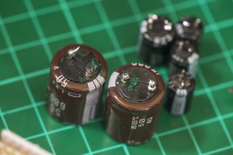
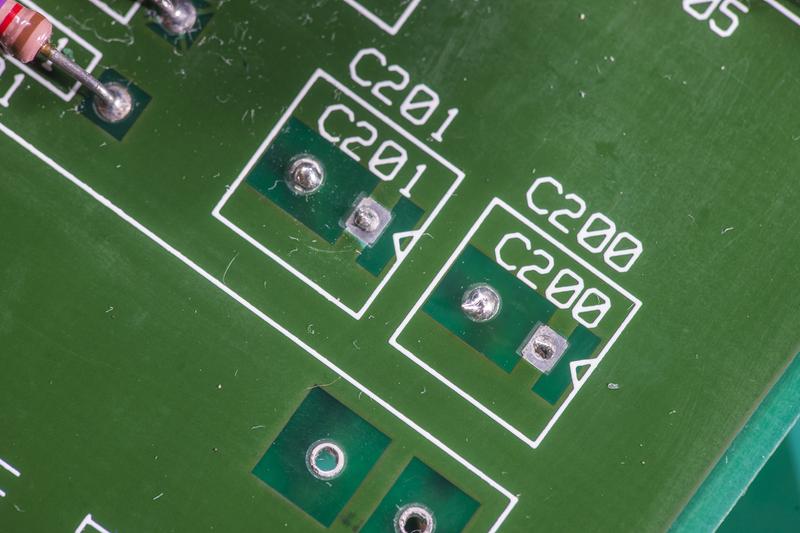

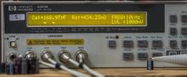
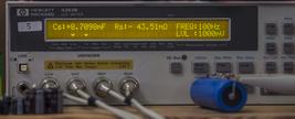
Everything assembled now, and ready for initial testing..
Transformer data for comparisons:
Voltage rail name | Nominal spec | Regulator | Bad transformer in our unit | New good transformer winding |
| +18V | +18VDC | U1, LM317T | Vmeas : 7.3 VAC, 0.5 Ω | Vmeas : 20.1VAC, 1.42 Ω |
| -18V | -18VDC | U2, LM337T | Vmeas : 6.9 VAC, 0.5 Ω | Vmeas : 20.1VAC 1.42 Ω |
| PSS | return for +-18VDC | Vmeas : 14.2 VAC, 1.0 Ω | Vmeas : 40.1VAC 2.88 Ω | |
| Resistance between ±18V winding and +5V | 0.5 Ω | >10 GΩ | ||
| -18unreg | CR01-CR04 diode bridge | |||
| +5V | +5VDC | U3, UA7805 | Vmeas : 7.0 VAC, 1.0 Ω | Vmeas : 9.1 VAC |
| -20V | -20VDC | CR17 zener + Pass PNP Q2 | ||
| Resistance between ±18V winding and secondary shield | 0.8 Ω Shorted! | >10 GΩ | ||
| Resistance between ±18V winding and secondary 5V shield | >10 GΩ | >10 GΩ | ||
And this is how transformer made:
Assembly timelapse :
Front panel reports REQUIRED ACAL ALL, then quickly passing TEST RAM, TEST CHECKSUM and advances to TEST HARDWARE.
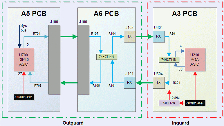
After about 5 seconds unit have one short beep and error message ISOLATOR FAILURE. This meaning digital side cannot talk to digital side of inguard section via isolation interface.
Here’s simplified block diagram of what interfacing look like:
If there is problem with either ASIC, it would be very hard to find replacement without buying new expensive boards. Let’s try troubleshoot issue on circuit level first, and hope for the best.
Optical cables are simple plastic fiber, and pretty easy to check, since used receivers and trasmitter are using 660nm light, which is visible red.
I can see red light on transmitter, and swapped cables without effect, having same error. When meter stuck on ISOLATOR FAILURE message it tries to send data, activating J102 Transmitter. If constant 660nm light directed on J101 receiver during meter power on, it resets itself in loop right after testing RAM, so likely that receiver path on A6 board is working.
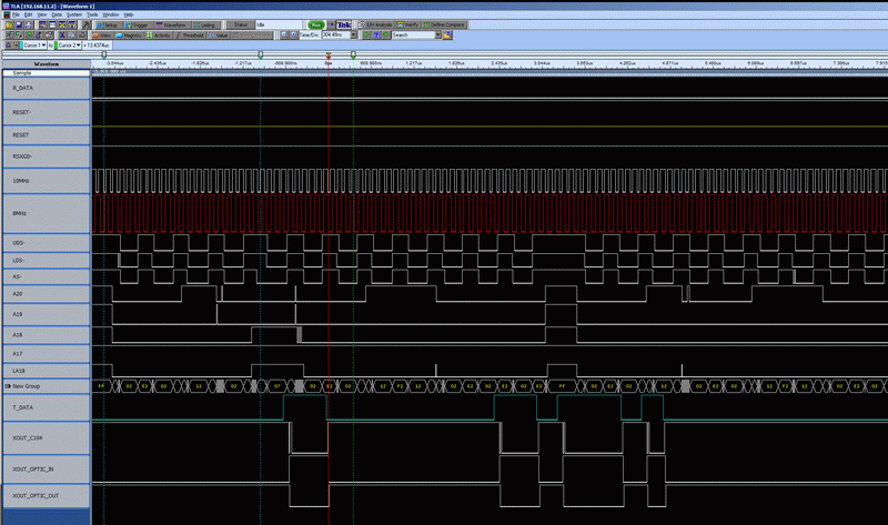
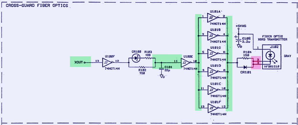
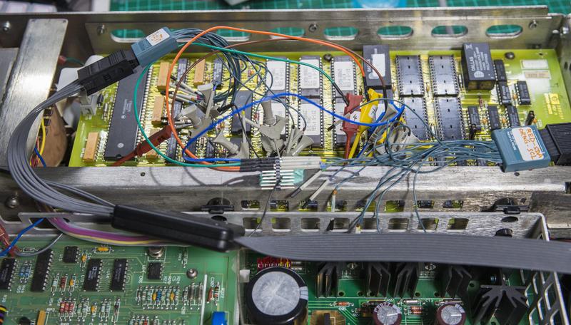
After some logic probing with my ancient Tektronix TLA714, I got idea that A5 is working okay, and problem narrow down to J102 transmitter interface
Signal path section on schematic of A6 PCBA:
One thing I notice before, LED light on J102 is really dim, could be also show actual problem with transmitter diode. Since it was easy, I actually swapped J102 with J303 before (which used for external triggering BNC ports), but result was same, so could be both transmitters are faulty.
To test this I had bypass transmit isolation path by adding a shorted between anode of A6 CR101 diode to U302 pin 9 input on A3 A/D board. Guess what, it booted and let me to UI.
It does lit up ERR with next errors:
202,“HARDWARE FAILURE — SLAVE TEST: CONVERGENCE”
110,“CALIBRATION REQUIRED — ACAL”
If I try run ACAL ALL, it says 205,“HARDWARE FAILURE — CAL VALUE OUT OF RANGE: 72” which is DCV A1 value, as per ALRM document.
That's some progress, if you ask me.
More to come, stay tuned...
Very impressive work so far, keep it up, im rooting for you to crack this thing
peter
Hi Illya,
This is better than a good mystery novel. I am eagerly awaiting the next chapter.
John
Fixed optical isolator issue, it was dead receiver on inguard A/D converter board. Swapped it with receiver from EXT trigger section (I don't need that now, will buy replacement part later) and bingo, it boots with optical isolation. 
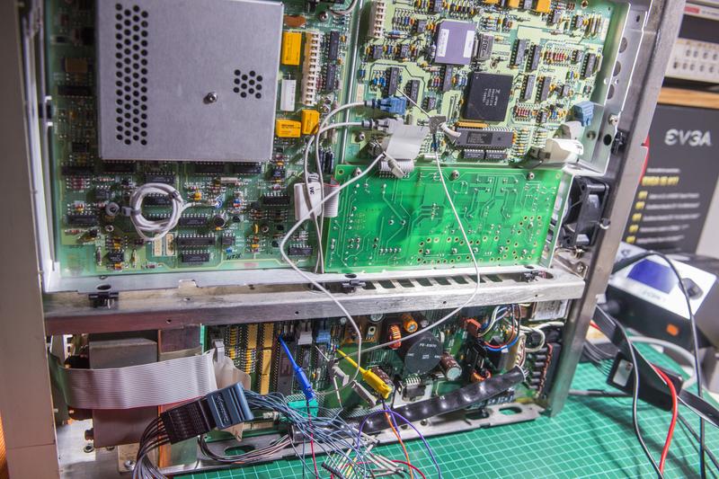
And guess what, yesterday was first time I ran out of hooks for LA... used total 21 inputs (out of 136 possible on my TLA7AA4  )
)
Decided to upgrade firmware for latest version... Only hardcore, only oldschool, using by bodged lamp to generate UV for UVEPROM erase, so I can flash chips.
Next steps
A1 DC board debug.
Current diagnosis:
DCV (any range) reading as near zero, but should be bouncing around on 10VDC and lower as it's >10GOhm impedance. So something somewhere cause too low impedance/short.
Ohms reading near zero for 10K and higher ranges, but OVLD for lower.
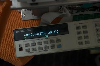
Current reading something microamps.
Forgot jumper near voltage reference, 
Now meter behaving much much better and can get first reading out of it!
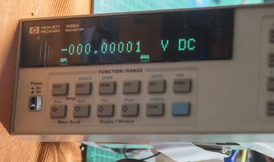
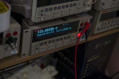
Measuring +10.0006 VDC from SMU:
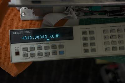
Ohms mode
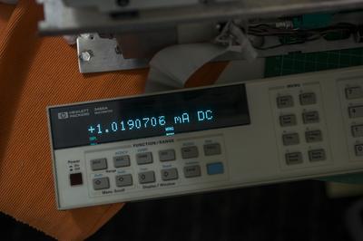
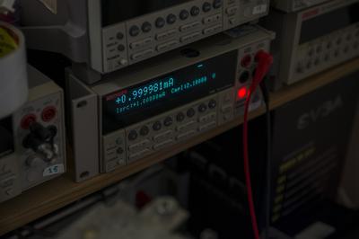
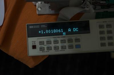
DCI ranges 10nA, 100nA, 1uA, 10uA, 100uA showin zero, no matter what current supplied into meter. So those ranges are broken. That cause self-test fail on value 95 as well.
DCI ranges 1mA and up are fine.
So happy now.
Video with Self-test, ACAL attempt and some tests.
Mystery solved. The Jumper did it.
Congratulations beautiful job.
John
Great post.
I agree, at first glance at the chassis I feared for the worst.
The inside boards look pretty good and I agree, a new transformer made good sense.
As you said, this is not an inexpensive rebuild, but you get a fantastic piece of gear for your efforts.
Thanks for sharing.
DAB
Thanks guys, you only following here, seems so 
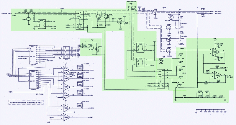
Since ranges 1mA and more working OK, we can rule out R210,R211,R212,R213 current shunt path, as well as input relays K201,K202,K203.
It is not likely that issue to be damaged JFET switches Q201-Q205 for low-current shunts R209-R206, as it’s less probable that all of them died.
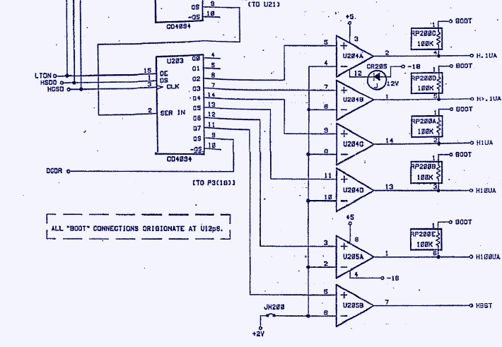
So I will test control circuitry first, which consists of U204 and U205 LM339 comparator for level shifting, U203 4094 shift register and RP200 generic resistor network and CR205 zener.
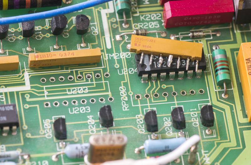
One thing we know from initial inspection – resistor network RP200 was re-soldered by previous owner. I have bought RP200 replacement before, just in case, so it could come handy.
I do have MC14094BCP replacement, left from Keithley 2001 repair project, in case I would need one.
HP's CLIP listed LM339 comparator as SELECTED, what would they select in it? Offset voltage?
I dont think it is important, the comparators are driving switches and as the common - rail is held at +2V and the output will be either +5 or -6 (or -18 on U205A/B) but nothing inbetween. I wouls say as long as the replacement will handle +-18V (+5 -18) you should be good to go
Nice work and very interesting. BTW how did you decide what replacement fan to use for the original Pabst 812L - did you see some specs for that one somewhere?
Woa, comment here  I used NMB 2410SB-04W-B20-B00 60x25mm 12V fan. Currently stuck with dreaded Error 114 - multislope rundown convergence, related to A/D board A3. Already spend over 50 hours on it, so far no crack. Going to replace A3 board to another one, I'm afraid. I maintain worklog on my site more actively. So you might want to check on progress there.
Here's current state of progress.
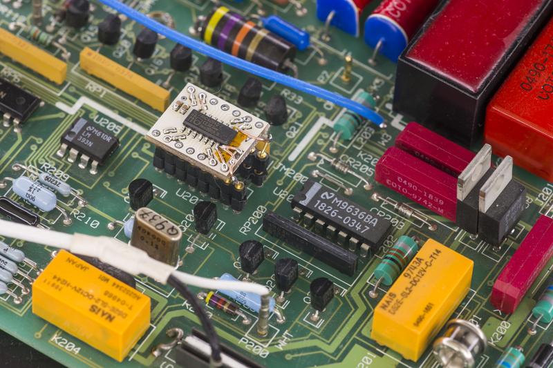
DCI low ranges were fixed:
I replaced U203 4094 mux, but likely problem was only RP200.
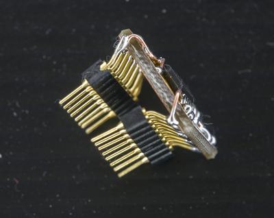
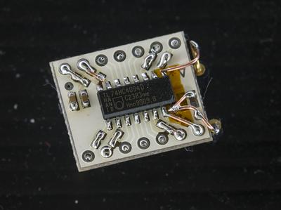
Bodged little SMD adapter for 4094, as I did not had proper DIP-version that time.
After removal both U203 and RP200, issue become obvious. RP200 missing common pin 1 for resistor array!
I replaced it with new 220Kohm 7-resistor SIP array. Worth to note, that schematics does show RP200 as pack of 100KΩ resistors, while BOM and actual A1 PCBA have 220K array installed.
I used 220K, following original part resistance value.
4094 handiwork:
Someone would say it’s wrong way to do things, but I was desperate to see unit working..
And it did, no problems on low current ranges anymore.
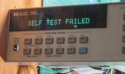
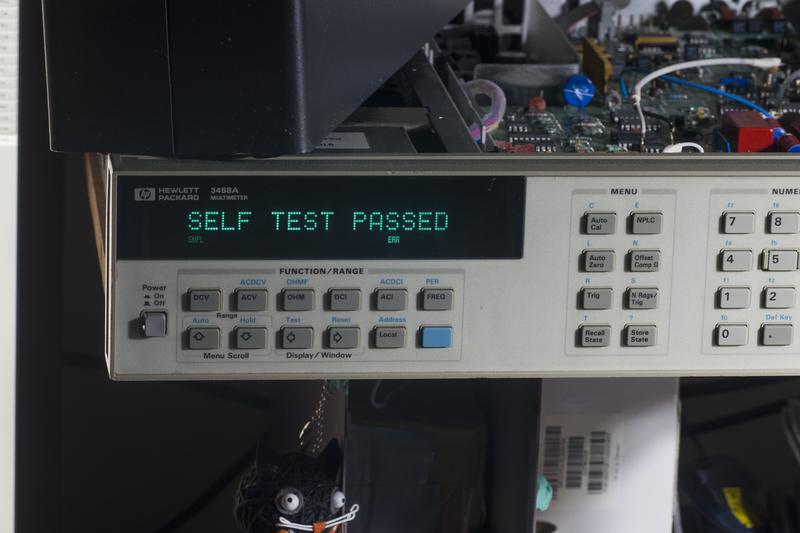
Unit also does complete whole selftest diagnostings. Was very happy to see this SELF TEST PASSED message after all the work we had done above.
I did also ACAL and it passed without problems.
SYSTEM ERROR 114 — multislope rundown convergence
Well, I left unit working overnight, just sampling 10VDC from Keithley 2400. No problems, did couple self-test runs, all pass with flying colors.
Then connected 1Meg resistance from ESI DB52 decade box and left it sampling for about 6 hours. After I come back to check on it, there was ERR lit and measurements halted. Pressing Enter key allow to do some measurements but it halted with ERR after few seconds.
Checking revealed ERRSTR 114 SYSTEM ERROR — multislope rundown convergence.
It does happen sometimes after a second, sometimes after three seconds on any DCV,DCI,OHM,OHMF functions, and does not occur on ACV,ACI,FREQ,PERIOD or digitize functions.
This error is not listed in repair manual, but there is Service note for Modification to Fix Intermittent Error “Multislope Rundown Conversion” which probably related and suggesting nothing else than replacing whole 03458-69503 A3 A/D Converter and Inguard Logic Assembly. This is not a good option for us, due to involved costs of new A/D board.
Spend so far over 50 hours trying to narrow down cause of this issue, tested lot of signals on A1 DC board, A2 AC board (later discovered this board is not in DC path which caused error), A3 A/D board.
Replaced comparators on A3 board, replaced most of opamps on it, tested resistors, did marginal testing on all power and reference rails injecting some currents into feedback to raise/lower voltages, did thermal margining, heating up different parts and even tried to cool U180 A/D switching/current control ASIC with TEC module. No luck. Going to replace A3 board now to see how it goes...
Got replacement A3 A/D board. Well, you guess correctly, dreaded ERROR 114 fixed, meter is working now.
,
More detailed video on repair.
Now meter working fine, left it running 24/7, will see if it keep that way. Hope so.
It is nice to see a bit of old equipment brought back from the grave.
Great project,
DAB
Can any body help me, how to upgrade the option 001 to option 002 for my 3458A DMM 8.5 ?
Welcome. You may want to read my article in detail https://xdevs.com/fix/hp3458a/ which covering those options.
To be short:
Option 001 - is 4 extra memory chips, which can be either 32Kx8 SRAMs or DS1230 Dallas NVRAM
Option 002 - is 4ppm/K voltage reference. If you want all genuine directly from Keysight, it will set you back for $984 USD + calibration would be needed.
If you still want to improve your reference stability, you can just do simple modification to reduce LTZ1000's temperature. That will cost $20-30USD for <3ppm/K 100K foil resistor and will make reference way more stable, if your ambient temperatures are lower than +35°C at all times.
This need recalibration as well!
Thanks for your information, and i have already started your article.
By the way as it is our master equipment, i need to send for re-calibration. so before that i think to upgrade the DMM to option 002.
But i am not aware of that which module is suitable for that and also please let me know that it is just the hardware installation or i need to programming anything?
please advice the option 002 module model no and also if possible can you provide the instruction to install it.
Hope that the model no is 03458-80003 .but i am not sure.
How old is your 3458A? If it's >10 years unit, you likely to already get performance of 002 level without any extra penny. Zeners do age with time, just like wine, and after few years they tend to be more stable than first time when they are being used. I have most of data you may need already in article, so read that first, and let me know if you have any questions left. There is no any firmware/programming needed for any of options, it's 1989 design man, no fancy firmware upgrades were popular back then.
For 001 just install memories and flip a jumper, for reference just swap A9 board or modify your existing one. But again, if your unit age is over 10 years, I would not bother, as it's stability is likely already reach it's best. Unless you really need every last ppm, but then you would not likely to ask questions in forums about that  .
.
Thanks you very much for your information.
Yes it is 10 years old.
May I know the option 002 module no in order to place the order.
And also i want to know that Part no: 03458-80003 and 03458-66519 is the same
Why you want an 002 then? Your reference is already aged well. You are likely to waste money for nothing, as if you get new module it will be drifting faster than your current one is! Temperature setpoint modification on your existing module will provide you best performance then, being much more stable than even 002.
Everything is assembled and ready to start testing...
Look on internals before installing shield covers:
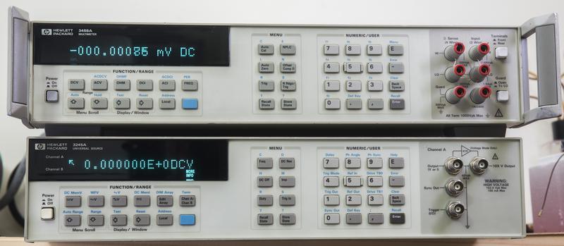
Also 6.5-decade DC/AC generator is ready to team with 3458A.
Good day to you sir,
And I wish you a happy new year 2016.
Now i have one unit of 3458A which is diplay problem, it doesnt show the full decimal points and also the LED is not so bright.
Could you please tell me the checking process to resolve it.
Hi, Can you elaborate more, what is problem? Do you get ERR messages? (you can check also if meter replies 0, NO ERRORS by pressing Blue key + "-"/Error key).
Also display is not LED, but VFD. These display age with time if being powered for long time with pixels lit. There is not much you can do to recover them (filament burn-in and drive current increase usually helps, but not for long/much).
Replacement is rather expensive too.
Hello Illya
This is was a really great repair report. It was a pleasure to read it. Thank you for sharing with us. Your website xdevs.com is also a really great place of very useful informations.
Kind Regards
Philipp
该文档由下列讨论生成:Worklog : Repair of 20-year old precision multimeter, HP 3458A


