element14 Community
element14 Community
    Register Log In
  • Site
  • Search
  • Log In Register
  • About Us
  • Community Hub
    Community Hub
    • What's New on element14
    • Feedback and Support
    • Benefits of Membership
    • Personal Blogs
    • Members Area
    • Achievement Levels
  • Learn
    Learn
    • Ask an Expert
    • eBooks
    • element14 presents
    • Learning Center
    • Tech Spotlight
    • STEM Academy
    • Webinars, Training and Events
    • Learning Groups
  • Technologies
    Technologies
    • 3D Printing
    • FPGA
    • Industrial Automation
    • Internet of Things
    • Power & Energy
    • Sensors
    • Technology Groups
  • Challenges & Projects
    Challenges & Projects
    • Design Challenges
    • element14 presents Projects
    • Project14
    • Arduino Projects
    • Raspberry Pi Projects
    • Project Groups
  • Products
    Products
    • Arduino
    • Avnet Boards Community
    • Dev Tools
    • Manufacturers
    • Multicomp Pro
    • Product Groups
    • Raspberry Pi
    • RoadTests & Reviews
  • Store
    Store
    • Visit Your Store
    • Choose another store...
      • Europe
      •  Austria (German)
      •  Belgium (Dutch, French)
      •  Bulgaria (Bulgarian)
      •  Czech Republic (Czech)
      •  Denmark (Danish)
      •  Estonia (Estonian)
      •  Finland (Finnish)
      •  France (French)
      •  Germany (German)
      •  Hungary (Hungarian)
      •  Ireland
      •  Israel
      •  Italy (Italian)
      •  Latvia (Latvian)
      •  
      •  Lithuania (Lithuanian)
      •  Netherlands (Dutch)
      •  Norway (Norwegian)
      •  Poland (Polish)
      •  Portugal (Portuguese)
      •  Romania (Romanian)
      •  Russia (Russian)
      •  Slovakia (Slovak)
      •  Slovenia (Slovenian)
      •  Spain (Spanish)
      •  Sweden (Swedish)
      •  Switzerland(German, French)
      •  Turkey (Turkish)
      •  United Kingdom
      • Asia Pacific
      •  Australia
      •  China
      •  Hong Kong
      •  India
      •  Korea (Korean)
      •  Malaysia
      •  New Zealand
      •  Philippines
      •  Singapore
      •  Taiwan
      •  Thailand (Thai)
      • Americas
      •  Brazil (Portuguese)
      •  Canada
      •  Mexico (Spanish)
      •  United States
      Can't find the country/region you're looking for? Visit our export site or find a local distributor.
  • Translate
  • Profile
  • Settings
Solar Power Devices
  • Challenges & Projects
  • Project14
  • Solar Power Devices
  • More
  • Cancel
Solar Power Devices
Blog Solar Bubble Blaster
  • Blog
  • Forum
  • Documents
  • Events
  • Polls
  • Files
  • Members
  • Mentions
  • Sub-Groups
  • Tags
  • More
  • Cancel
  • New
Join Solar Power Devices to participate - click to join for free!
  • Share
  • More
  • Cancel
Group Actions
  • Group RSS
  • More
  • Cancel
Engagement
  • Author Author: fmilburn
  • Date Created: 7 Aug 2018 5:32 AM Date Created
  • Views 6865 views
  • Likes 20 likes
  • Comments 32 comments
  • solar panel
  • super capacitor
  • pump
  • bubble blower
  • solarpwrdevicesch
  • motor
Related
Recommended

Solar Bubble Blaster

fmilburn
fmilburn
7 Aug 2018

image

Summary

The Solar Bubble Blaster is the first super capacitor enabled bubble blower to be powered by the sun.  Saving the earth, one bubble at a time, there are no batteries required.

Background

This summer time project was done with my grandchildren.  Our objectives were to learn about converting solar energy into useful "work" and have fun.  With the exception of the hacked bubble blower all of the components were things I had in my junk box and parts cabinet.  The project ended up working better than expected.

Development

I had a small solar panel rated at 0.5W, 6V that I picked up at the local Radio Shack when they went out of business and were selling inventory at a discount and a small inexpensive water pump we started with.  As expected, the solar panel could not power the pump by itself so we added some super capacitors (two 1F and a 2F) that I had collected over time.  A 5.1 V Zener diode was used to control the voltage so that the 5.5 V rating of the super capacitors was not exceeded.

image

Having successfully demonstrated that the super capacitors could power the pump for at least a short period of time we began collecting additional data for an IV curve using 1% tolerance resistors as a load.

  image

Data was taken on a beautiful sunny day here in Seattle around 15:00 at a temperature of 21 degrees C with 48 % humidity.  The panel was not optimally aligned with the sun.  The open circuit voltage was around 6.6 V and the flat part of the curve at about 44 mA.  The maximum power point (MPP) occurred just over 5V  under these conditions and the panel generated about 0.22 W.

The data was scattered and I wanted to go back and repeat data collection with different panel alignment but the kids had lost interest and had gone off to blow bubbles with their grandmother.  This gave me the idea to power a bubble machine and I found and purchased a “Blitz” Light-up Bubble Blaster on sale for $3.99.

image

Preliminary Design

That night the Bubble Blaster was dissected to see how it worked and it turned out to be a very interesting device.  Disassembly was easy since screws were used throughout.  The main mechanism is shown in the photo below.

image

Three alkaline 1.5 V batteries provide the power. The trigger serves as a switch and powers the small motor directly.  A ceramic capacitor is soldered across the poles of the motor.  A worm gear is attached to a shaft on the bottom of the motor and drives a gear mechanism with a peristaltic pump for the bubble solution. The bubble solution is pumped to a serrated aperture at the front of the gun.  Another gear mechanism at the top of the same motor drives a fan which blows bubbles out of the aperture.  Also visible are red and white wires which are attached to a “blob” which controls the LEDs.  All for $3.99!

I hooked up the Bubble Blaster to my bench power supply with voltage set to 4.5 V and measured around 330 mA current with no soap solution being pumped.  Wires were then soldered to the positive and negative battery contacts so they could be connected to a breadboard.  The solar panel was also connected to the breadboard along with the super capacitors and a 5.1 V Zener to control voltage.

  image

In the photo we see that the solar panel is charging the super capacitors up to 5.24 V.  After playing around with it a bit we found that to get good performance all three super capacitors were required.  In the past I had measured the actual capacitances and found them to be at the low end of their ratings (especially the inexpensive 1F rated ones from China) and I suspect actual capacitance of the three in parallel is something around 2.5F.  There is frequently a -30% tolerance on these capacitors but I don't have a datasheet for the 1F capacitors.

Fabrication and Lab Test

That evening I soldered the following circuit on a small piece of protoboard cut to size.

image

The IN4148 diode prevents the super capacitors from discharging back through the solar panel when there is reduced light.  The 5.1V IN4733A Zener (+/- 5%) sets the voltage to the super capacitors at a measured 5.25 V and also serves as a snubber diode for back EMF protection from the motor when the trigger switch is opened. All three capacitors are in parallel. The motor wiring and LED wiring was left unchanged.

Sometimes a current limiting resistor is added in the circuit above but I did not see a reason for it in this case.  To better understand how it behaved an oscilloscope was connected and the circuit charged up with a bench power supply.  The power supply was then disconnected for the test shown below so that only the super capacitors are providing power.

image

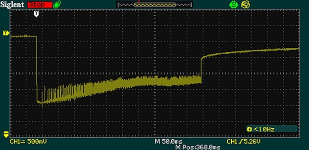
The vertical divisions are at 500 mV and the starting voltage is 5.26 V.  The horizontal divisions are 50 ms.  When the Bubble Blaster trigger is pulled the inrush current causes the voltage to drop to almost 3.5 V.  It then begins to recover while showing a lot of noise.  After approximately a second when the trigger is released there is immediate recovery to about 4.5 V with additional slow recovery afterwards. From this I decided the circuit was performing OK, at least for a toy.

The battery compartment was hollowed out and the super capacitors and new circuitry inserted.  Enough plastic was left so that the batteries could still be reinstated should that be desired in future.  The device was reassembled, the solar panel hot glued to the top, and everything made ready for field testing.  Preparation included priming the pump with power from the bench power supply and blowing a few bubbles in the lab.  Current was closer to 400 mA when pumping liquid soap.

image

image

Field Test

The field tests were performed on 3 August 2018 at around 14:00 in full sun on another beautiful day with 21 degree C temperature. In one test we measured the starting voltage at 5.23 V and the device blew bubbles for approximately 15 seconds before stopping.  Recharge to 5.20 V took approximately one minute.


You don't have permission to edit metadata of this video.
Edit media
x
image
Upload Preview
image

One shortcoming is that it is possible to hold the trigger after voltage drops and the bubbles stop.  This causes the capacitors to discharge more than necessary which increases the time to recharge.  I considered adding something to turn off the device at a fixed low voltage but in the end the kids learned to stop pulling the trigger when the bubbles stopped.  Obviously solar charged batteries could have been used and this would have provided longer time between charging (as well as longer charging time).  But super capacitors just seem so much cooler.

Thanks for reading.  As always, comments and suggestions for improvement are appreciated.

  • Sign in to reply

Top Comments

  • jw0752
    jw0752 over 7 years ago +6
    A magic project that only a grandpa can think up and bring to reality. I loved it. John
  • michaelkellett
    michaelkellett over 7 years ago in reply to drmikeg +6
    You'll get a slightly better performance if you use a schottcky diode in place of the 1N4148 MK
  • 14rhb
    14rhb over 7 years ago +5
    Hi Frank, A great project showing the fun to be had with electronics. Storing the solar energy to drive more powerful devices, albeit for a shorter duration, is definately cool. And when the sun isn't…
Parents
  • drmikeg
    drmikeg over 7 years ago

    Amazing!
    I started a thread a while ago to ask if anyone could give me some pointers on doing just this!
    https://www.element14.com/community/thread/64034/l/convert-toy-motor-to-solar-power-where-to-begin

    Well, now I have more than just a few pointers!

    Best wishes and many thanks for sharing in such detail!

    • Cancel
    • Vote Up +4 Vote Down
    • Sign in to reply
    • More
    • Cancel
  • michaelkellett
    michaelkellett over 7 years ago in reply to drmikeg

    You'll get a slightly better performance if you use a schottcky diode in place of the 1N4148


    MK

    • Cancel
    • Vote Up +6 Vote Down
    • Sign in to reply
    • More
    • Cancel
  • ntewinkel
    ntewinkel over 7 years ago in reply to michaelkellett

    >You'll get a slightly better performance if you use a schottcky diode in place of the 1N4148


    Hi Michael, could you explain a little more on that?  What's the difference?

    This is something that's come up before and to be honest I'm kind of lost in that area.


    My rough understanding is that the schottky diode loses less voltage than the regular 1N- diode? But was that part of the plan? Frank's drawing indicates expected input voltage of 6.6v and output of 5.2v (or is that regulated by the zener diode?)

    Also, is there a specific part number you'd recommend?


    Related to that question is the zener diode in that circuit... do those become a short above the set voltage?  ie, does it need an additional resistor?


    Thanks!

    -Nico "lost in the circuitry again"

    • Cancel
    • Vote Up +4 Vote Down
    • Sign in to reply
    • More
    • Cancel
  • genebren
    genebren over 7 years ago in reply to ntewinkel

    Nico,


    Your question about the Zener is a good one.  Typically, I would want to have a current limiting resistor in-line with the zener.  But in this case, the solar panel will act as a limiting resistor.  As excess current is drawn from a solar panel, the voltage drops.  This voltage drop should protect, and in a strange way regulate the circuit to the zener voltage drop.

    Also, the schottcky diode would not really help, except in a very narrow window, where the solar panel is not fully illuminated and is only producing slightly more than the zener voltage.


    Gene


    • Cancel
    • Vote Up +4 Vote Down
    • Sign in to reply
    • More
    • Cancel
  • fmilburn
    fmilburn over 7 years ago in reply to genebren

    Hi Michael, Gene and Nico,


    Thanks for confirming that my thought process was basically good.  I appreciate especially the description of why it works without the resistor which I considered and experimented with a bit.  The post is getting a fair amount of hits as a friend of mine sent a tip to hackaday and they had a little write-up.  It is nice to have the clarifications and comments.

    • Cancel
    • Vote Up +5 Vote Down
    • Sign in to reply
    • More
    • Cancel
Comment
  • fmilburn
    fmilburn over 7 years ago in reply to genebren

    Hi Michael, Gene and Nico,


    Thanks for confirming that my thought process was basically good.  I appreciate especially the description of why it works without the resistor which I considered and experimented with a bit.  The post is getting a fair amount of hits as a friend of mine sent a tip to hackaday and they had a little write-up.  It is nice to have the clarifications and comments.

    • Cancel
    • Vote Up +5 Vote Down
    • Sign in to reply
    • More
    • Cancel
Children
  • fmilburn
    fmilburn over 7 years ago in reply to fmilburn

    A bit more clarification on choosing whether to put a resistor in front of the diode and capacitor.  In the case that the Zener begins to allow current flow, and the resultant current causes the power rating of the Zener to be exceeded, a resistor could limit current and protect it. In this particular case the solar panel is rated at 0.5 W and the Zener at 1 W so protection is not needed.

    • Cancel
    • Vote Up +3 Vote Down
    • Sign in to reply
    • More
    • Cancel
element14 Community

element14 is the first online community specifically for engineers. Connect with your peers and get expert answers to your questions.

  • Members
  • Learn
  • Technologies
  • Challenges & Projects
  • Products
  • Store
  • About Us
  • Feedback & Support
  • FAQs
  • Terms of Use
  • Privacy Policy
  • Legal and Copyright Notices
  • Sitemap
  • Cookies

An Avnet Company © 2025 Premier Farnell Limited. All Rights Reserved.

Premier Farnell Ltd, registered in England and Wales (no 00876412), registered office: Farnell House, Forge Lane, Leeds LS12 2NE.

ICP 备案号 10220084.

Follow element14

  • X
  • Facebook
  • linkedin
  • YouTube