

Hello everyone!
Here is a fairly well-known circuit, and still good to build. First, by way of comparison, I want to show you a beautiful presentation from an older electronics magazine, circulating a long time ago, around the early 2000s.
"The presented audio amplifier is made using the TDA2030 integrated circuit. In the monophonic version, the amplifier, correctly made, will have characteristics such as:
- sinusoidal continuous output power: 15W/18W;
- musical power: 25W;
- input impedance: 150kΩ;
- voltage gain: 30dB;
- reproduced frequency band: 2Hz...30kHz;
- absorbed current: 1-1.3A.
At the output, the TDA2030 circuit has high current capability, with very low harmonic and connection distortions. The input sensitivity is 300mV. The power supply is made from a well-filtered voltage source that can provide up to +35V at a current draw of 1.2A.
The voltage amplification of the assembly can be modified (when necessary) by juggling the values of resistors R4 and/or R5, as follows: Au = 1+ R5/R4 In the case of a large amplification there is a risk of oscillations, which leads to the failure of the basic component, namely the integrated circuit.
A load (acoustic enclosure) with an impedance of 4Ω is connected to the output. The TDA2030 integrated circuit is mounted on a radiator without electrical insulation. The total surface area of the heat sink used must be
about 300cm2.
When put into operation, the assembly does not require any adjustment."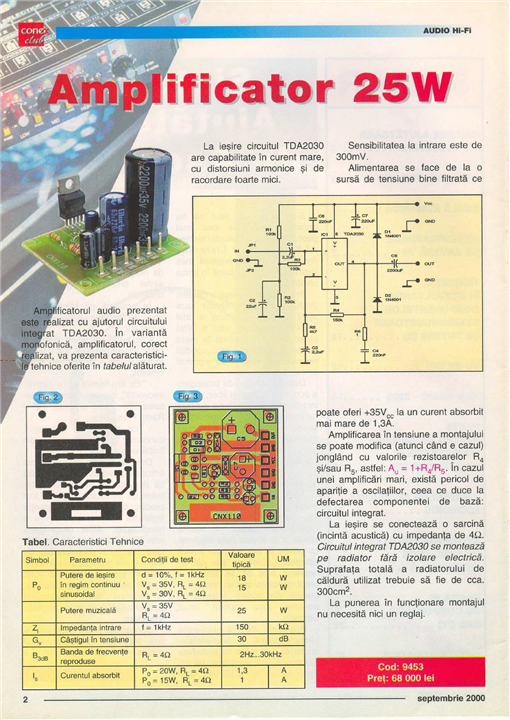
I used the electronic diagram from the datasheet (https://www.st.com/resource/en/datasheet/tda2030.pdf), most likely the manufacturer of my component is not the same.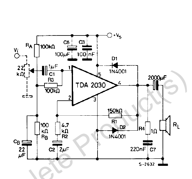
PCB design
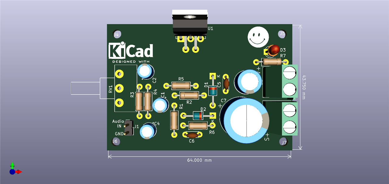
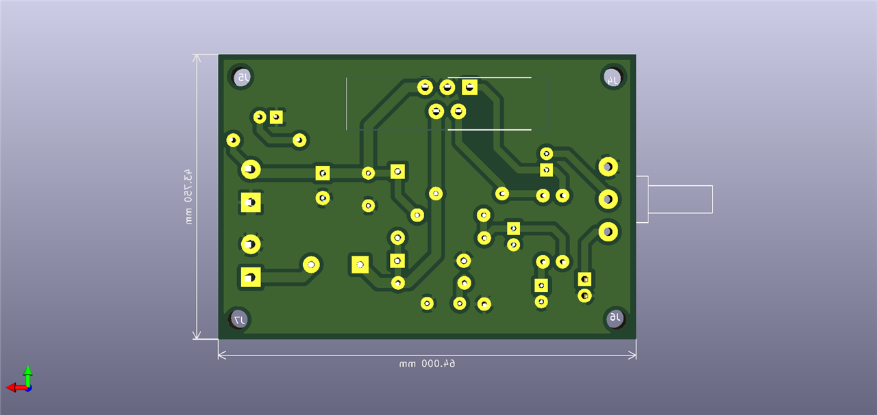
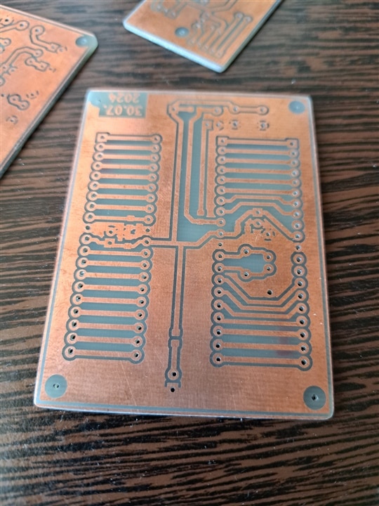
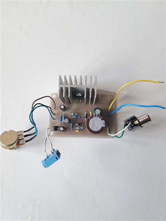
The PCB is designed in KiCAD, an easy-to-use program for people with no pretensions, like me. Single layer, 64mm*44mm, finished about a year ago and finally put into operation.
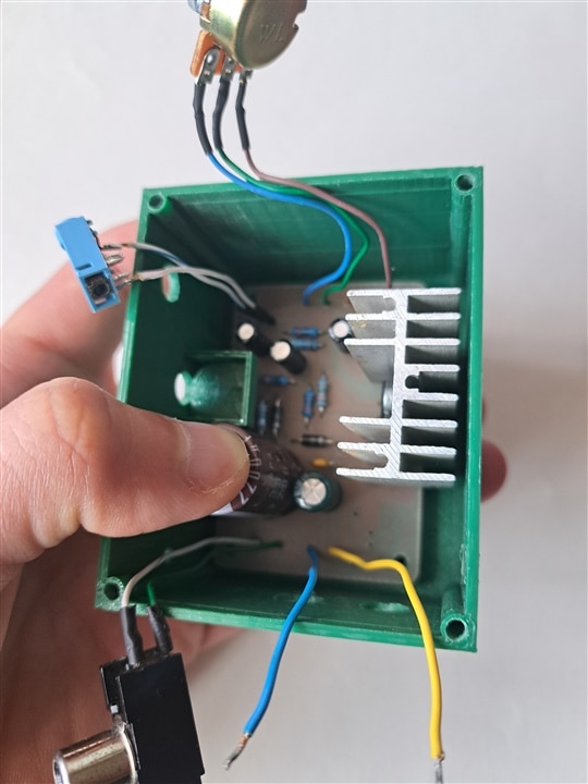
At the level of electronic components I use a certain practice, reusing components from other electronic boards ( ). Obviously I was not able to do this for all the components, the potentiometer is new, the DC jack and the switch, 1-2 capacitors (I was lucky to find the big one on a board) and also 1-2 resistors because I didn't have the value. It is very likely that the radiator will be a bit small, but this amplifier will not be stressed, I don't want to bother the neighbors.
I also have other TDA circuits, I also have a project with 2x TDA2030 for which I need to build a case, this one is bulkier, has large radiators, but I will finalize it soon.
| {gallery}KiCAD |
|---|
|
PCB Top |
|
PCB Bottom |
Making the PCB
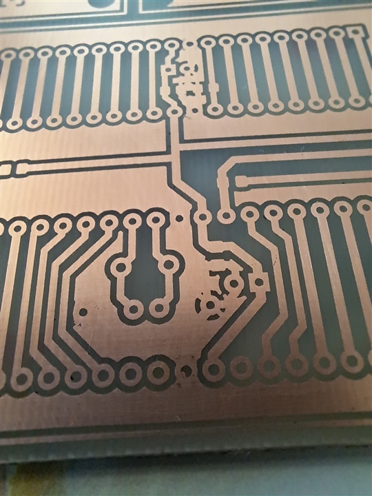
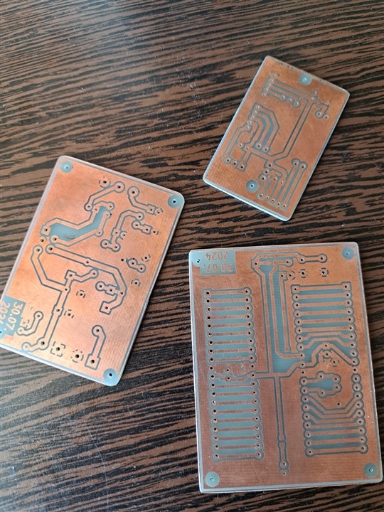
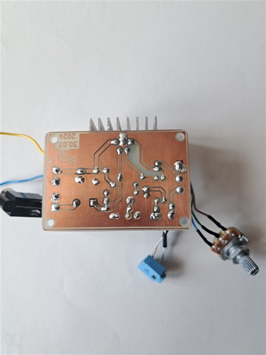
The PCB is made in a manner that is neither homemade nor professional. I used to make homemade PCBs using the thermal transfer method (with an iron on clothes and so on), but this time I needed a little more precision and therefore I turned to a workshop that deals with customization of items and other materials (mugs, posters, things like that). They have a kind of powder printer I would say because if you scratch the traces, they are erased. Next, I try to do the etching process very carefully. I soldered several small PCBs in a single project then I transferred them to the copper plate, cutting, separating and drilling them was my job.
| {gallery}Making the PCB |
|---|
|
|
|
|
|
|
|
|
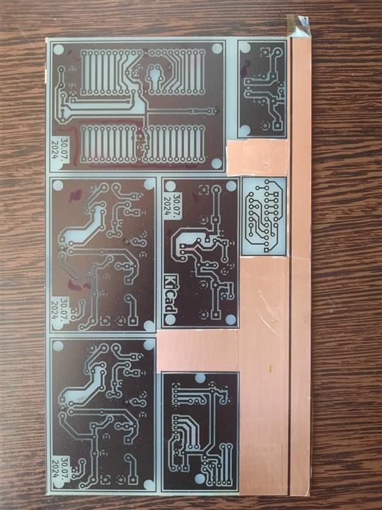
It cost me about 6 EUR to make the boards (as a single piece), but I was really happy with the result. 
I have copper-plated boards, I clean them well with dishwashing detergent, a sponge and, be careful, sand, yep, because they are not very clean and sand helps with that.
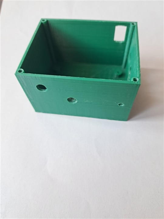
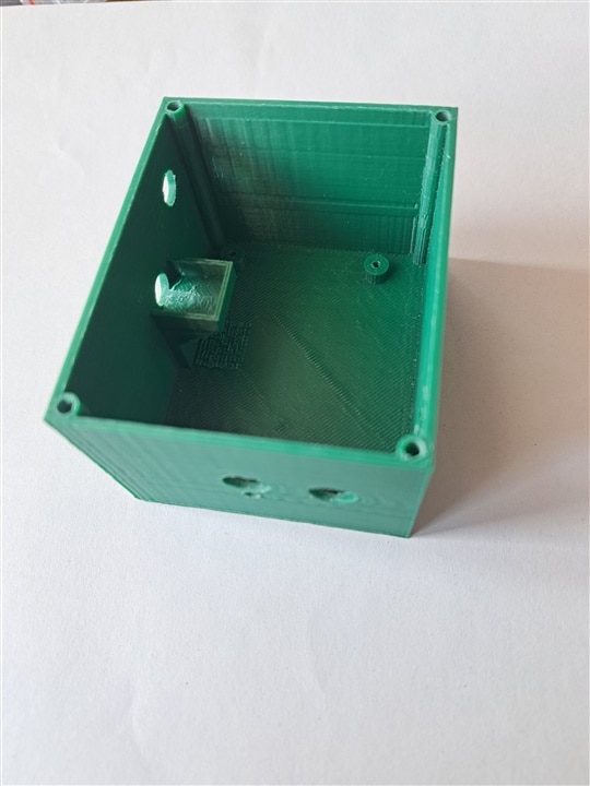
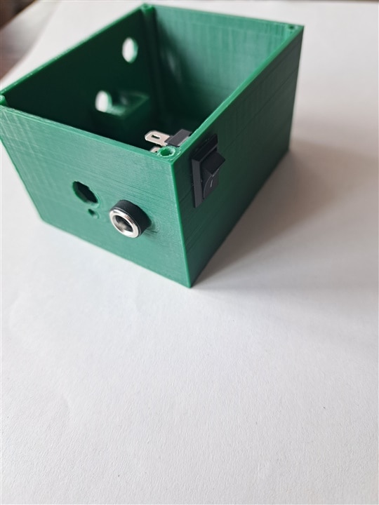
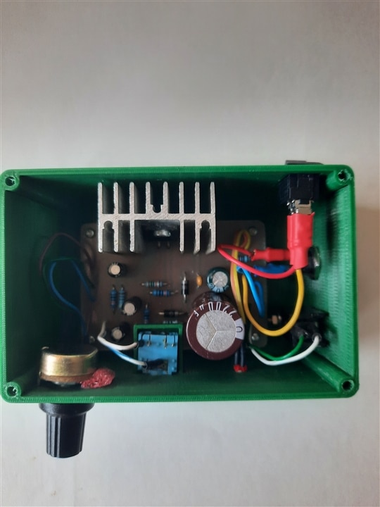
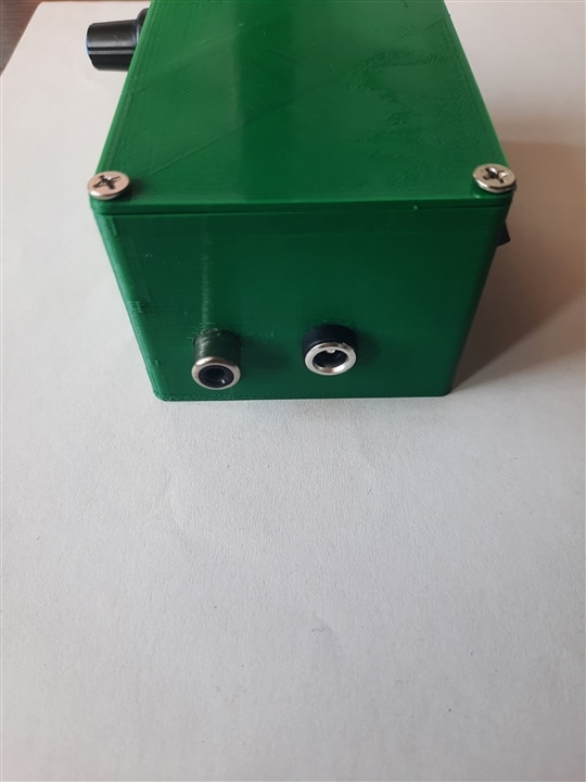
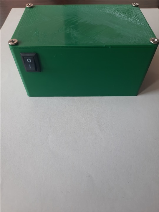
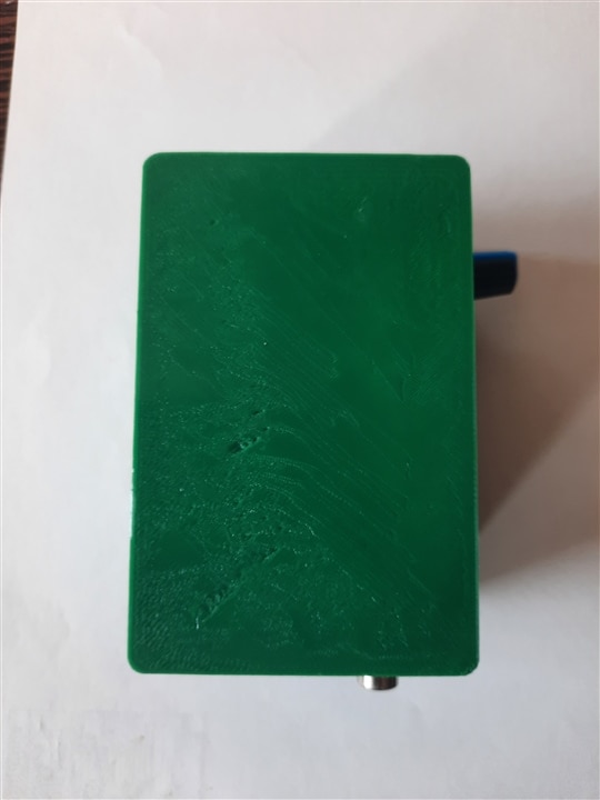
Making the 3D case
For such a custom PCB I also needed a case, and I tried something 3D printed from PLA material (I have a friend who owns a 3D printer) but the first case is a half-failure one because I crowded all the parts, it seems that my math starts with -10, or -10mm, that's about how much I left out of the case size. The RCA jack doesn't fit, and the DC jack and switch don't fit very well either, so the new version is a bit bigger (92mm*60mm*45mm). I used TinkerCAD because it's free and it's enough for what I'm building.
| {gallery}First 3D printed enclosure |
|---|
|
|
|
|
|
|
|
|
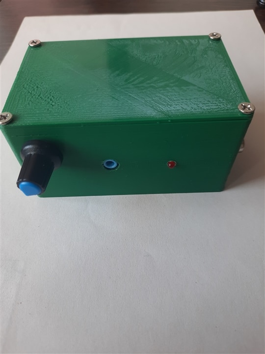
I also made other small improvements including rounding the corners. 
I have a short demonstration video. For the test I used a simple speaker (I don't have anything else available here and now) that I had in a box, I think it's a woofer, there's no information written on it, and as a 12V power supply I have something slightly modified, an ATX from a computer.
| {gallery}Finish |
|---|
|
|
|
|
|
|
|
|
|
|
|
|
|
|
|
|

Video:
Back then, I was thinking of attaching the audio amplifier to a desktop PC (somehow ) but now I've given up on the desktop, a laptop is good enough and more practical.
Enjoy it and have a great day!
