


Intro
I use digital calipers on every project which makes me interested in their features. With the advent of low-cost digital calipers, I could not resist buying a couple of them. I discovered they have several drawbacks such as jerky friction, very short battery life and low resolution. However they do have a connector that can be used to monitor their readings. I have been looking for an interface cable for years, and there are some, but they are far more costly than the calipers, so I started looking into making my own. This is not a new idea, but all the home made connectors I have seen have problematic connectors. Usually they have no springs in the contacts, which makes it hard to maintain reliable contact on all four pins. I discovered quite a few issues that slowed my progress down significantly. One of the main issues was determining the pitch of the pins. I needed to be sure of the pitch because my plan was to make a printed circuit board with a custom connector and I didn't want to re-do it. This blog is the culmination of that journey.
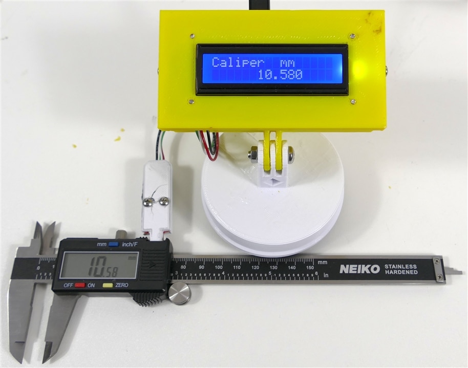
E-Caliper System Image
Digital Caliper Interface Schematic
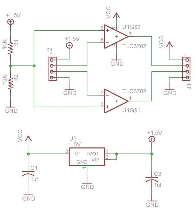
This circuit translates the1.5V clock and data signals from the caliper to 3.3V or 5V. It has a 1.5V regulator to supply power to the caliper and the voltage divider that sets the comparator voltage for the dual comparators. The supply voltage for the comparators is 3.3V or 5V, what ever supply voltage is coming from the MCU. I actually substituted an MCP6002 op-amp for the comparator s since that is what I have in stock, and it worked perfectly. I looked at the signals on a scope and they are very clean. The scope was needed to nail down the relationship and timing of the clock and data signals.
Digital Caliper Interface PCB
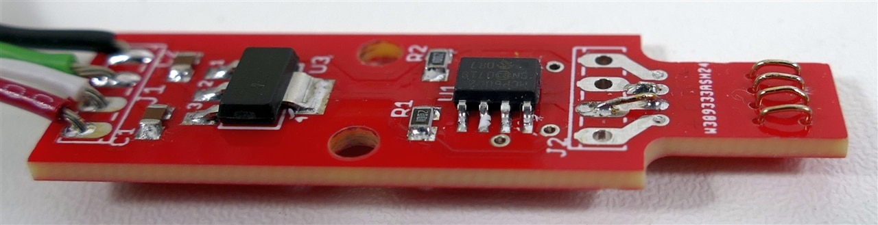
Note the four custom spring contacts that need to mate with digital caliper PCB plated fingers. The pitch between pins that I used is 1.5mm and it seems to work, but it is pretty fiddly to accurately form these small contacts at such a fine pitch.
MCU Schematic
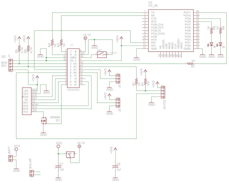
This PCB connects an HC05 Bluetooth module to a an Arduino Pro Micro. It also has an I2C 1602 LCD to remotely display the caliper reading. Th LCD uses 3.3V I2C pullup resistors, but the power supply is 5V to allow high LCD contrast. Of course it also dedicates 2 pins to receive clock and data caliper signals.
MCU Module
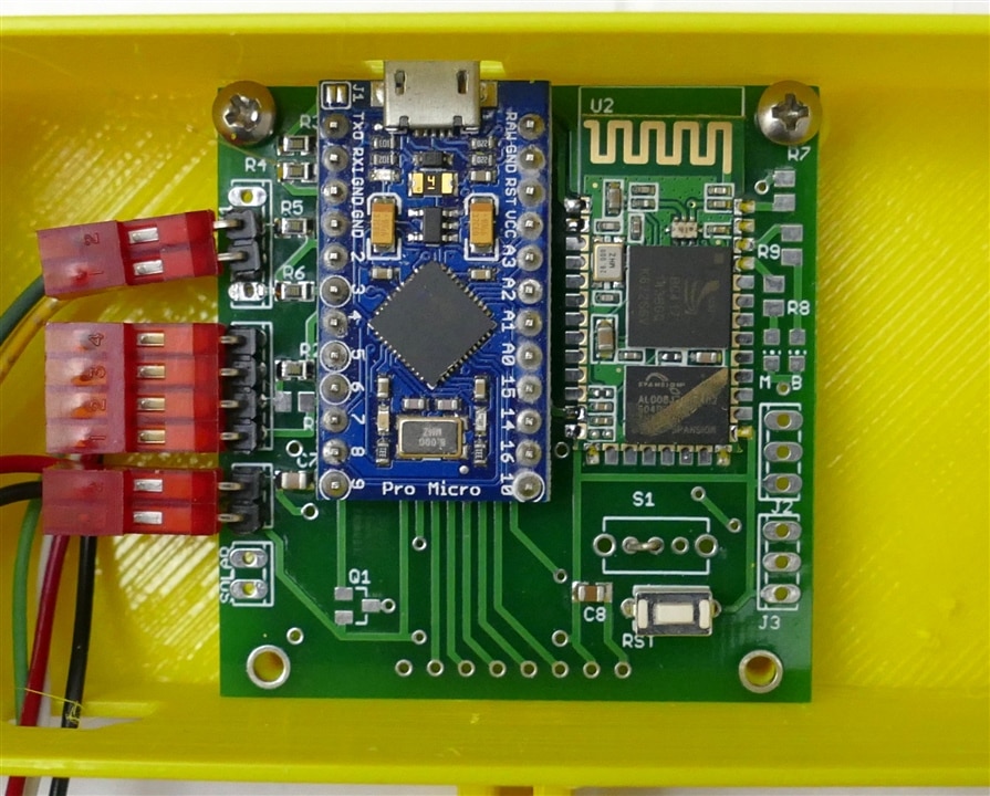
The Bluetooth module was programmed with the name of "Caliper" to make identification in the Bluetooth device lists easier. The programming system for the Bluetooth module was the subject of a recent blog.
E-Caliper Video
Firmware
// Caliper sketch to read and display caliper readings
// Readings are sent to LCD, Bluetooth and USB
// by Doug Wong 2025

#include <Wire.h>
#include <LiquidCrystal_I2C.h>

#define CALIPER_CLK A2  // Clock pin from caliper
#define CALIPER_DATA 5 // Data pin from caliper

LiquidCrystal_I2C lcd(0x27, 16, 2); // Adjust the address if needed

int bit_array[25];        // For storing the data bit. bit_array[0] = data bit 1 (LSB), bit_array[23] = data bit 24 (MSB).
unsigned long time_now;   // For storing the time when the clock signal is changed from HIGH to LOW (falling edge trigger of data output).
unsigned long ms_now;
float LastValue;

void setup() {
    pinMode(CALIPER_CLK, INPUT);
    pinMode(CALIPER_DATA, INPUT);
    lcd.begin();
    lcd.backlight();
    lcd.setCursor(0, 0);
    lcd.print("Digital Caliper");
    lcd.setCursor(0, 1);
    lcd.print("   Readout");
    delay(500);
    lcd.clear();
    lcd.setCursor(0, 0);
    lcd.print("Caliper ");
    Serial.begin(38400);
    Serial1.begin(9600);
    Serial1.println("digital Caliper");
    pinMode(17, OUTPUT);
}

void decode() {
  int sign = 1;
  int i = 0;
  float value = 0.0;
  float result = 0.0;

  while (digitalRead(CALIPER_CLK) == LOW) {};       // Wait until clock is HIGH

  for (i = 1; i <= 24; i++) {
    while (digitalRead(CALIPER_CLK) == HIGH) { }    // Wait until clock goes LOW
    bit_array[i] = !digitalRead(CALIPER_DATA);
    while (digitalRead(CALIPER_CLK) == LOW) {};
  }

  for (i = 1; i <= 20; i++) {                       // Turning the value in the bit array from binary to decimal.
      value = value + (pow(2, i-1) * bit_array[i]);
  }

  if (bit_array[21] == 1) {
    sign = -1;                      // Bit 21 is the sign bit. 0 -> +, 1 => -
  } else {
    sign = 1;
  }

 if (bit_array[24] == 1) {          // Bit 24 indicates the measuring units (1 -> in, 0 -> mm)
     lcd.setCursor(9, 0);
     lcd.print("inches ");
     result = (value*sign) / 2000.00;
     lcd.setCursor(6, 1);
     lcd.print(result, 4);          //send result to LCD
     lcd.print("  ");
     Serial1.print(result, 4);      //send result to Bluetooth
     Serial1.println(" in  ");
     Serial.println(result, 3);     //send result to USB
     Serial.println(" in  ");
  } else {
     lcd.setCursor(9, 0);
     lcd.print("mm     ");
     result = (value*sign) / 100.00;
     lcd.setCursor(6, 1);
     lcd.print(result, 3);          //send result to LCD
     lcd.print("  ");
     Serial1.print(result, 3);      //send result to Bluetooth
     Serial1.println(" mm  ");
     Serial.print(result, 3);       //send result to USB
     Serial.println(" mm  ");
  }
}

void loop() {                                      //detect start of data reading sequence
    if (digitalRead(CALIPER_CLK) == HIGH) {
      while (digitalRead(CALIPER_CLK) == HIGH) {}  // Wait for clock to go LOW
    }
    time_now = millis();
    while (digitalRead(CALIPER_CLK) == LOW) {     // Wait for clock to be LOW for 10ms - only happens between readings
      if ((millis() - time_now) > 10) {break;}
      if (digitalRead(CALIPER_CLK) == HIGH) {time_now = millis();}
    }
    decode();                                     //capture and decode the bit sequence
}
A couple of things to note:
- The data stream for one reading is 24 bits. Bit 24 indicates whether the reading is in inches (1) or mm (0)
- Bit 21 is a sign bit - if it is 1 it means it is negative number
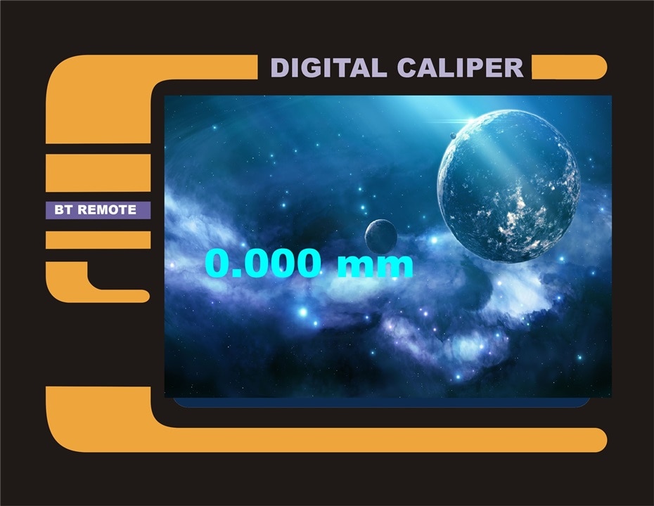
Discussion
I am glad that I finally got a digital caliper interface working after so many moons of scratching at the edges of it, and I am very happy that the PCB I designed fit well and worked flawlessly. The project started out seeming to be simple, but It ended up with four 3-D printed parts, 2 PCBs, a PC and an android device. The firmware is not long, but without closely examining the scope traces and going through numerous revisions, it would not have worked. Those fancy custom contacts have already been through dozens of mating cycles with no apparent degradation. There are a couple of things I could do to improve on the prototype and I have nine more PCBs available if I get ambitious, but the main objective of this project has been met. One thing I have already started is an android app to display the readings sent via Bluetooth. here is a preview of what it will look like:
I will try to add in a scope image of the clock and data waveforms to this blog. They are quite interesting, but I have to take the system apart to get a scope on the signals.
This project is not exactly spring cleaning, but the theme includes digging out old projects, and the project does have some nifty spring contacts in it...


