


A few months back while looking for information on oscillators, I stumbled across a 40dB tap. Okay, the article was really about a RF power meter, but that looked complicated and, besides, I already have a NanoVNA. I would really like to NOT blow up the NanoVNA so the tap caught my eye. The article is from the June 2001 edition of QST magazine by the ARRL. The authors are Wes Hayward and Bob Larkin. The article is attached below.
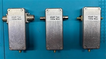
So... I ordered the little aluminum enclosures. Of course they come in a three pack. Fine. I need 1.5 inches of a brass strip. It comes in a 12 inch strip. Fine. I need a SMA bulkhead connector. They come in 5-packs. Fine. I don't have resistors of the correct power rating. I can get 100 for the same price as 10. Fine. With all this excess material, I'll make a SO-239 version, a BNC version and a SMA version. It's a bit more than I was thinking about, but they will save me from using a bunch of adapters. This is a good thing.
So I built the SO-239 version. It turned out nice. It turned out that it wasn't quite as easy to build as I estimated AND... I built the easy one - the one in the article. So the project stalled. Onto the next bright shiny thing.
And the other versions? The only movement they have seen was to get pushed out of the camera shot for the 2-year antenna project.
In the spirit of Spring Clean, let's get this project completed.
Fantastic. I have just started and I'm using up all of the M2.5 hardware from my standoff kit. I need to order some hardware. Maybe this was why I stalled out a few months ago. At least I was able to find all of the SMA bulkhead connectors. The brass strip is still at the end of the work bench where I do my sawing. It hasn't moved in months. Even the resistors are still here – albeit buried under other stuff.
On a bright note, my custom brass plate feedline installation jig is still here as well.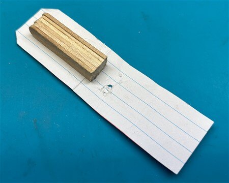
The build isn't super complicated. Here was the starting point. You can see that I started drilling some of the mounting holes while I waited for the M2.5 hardware. Both the SO-239 and the SMA connector mounting holes were tapped into the body of the enclosure.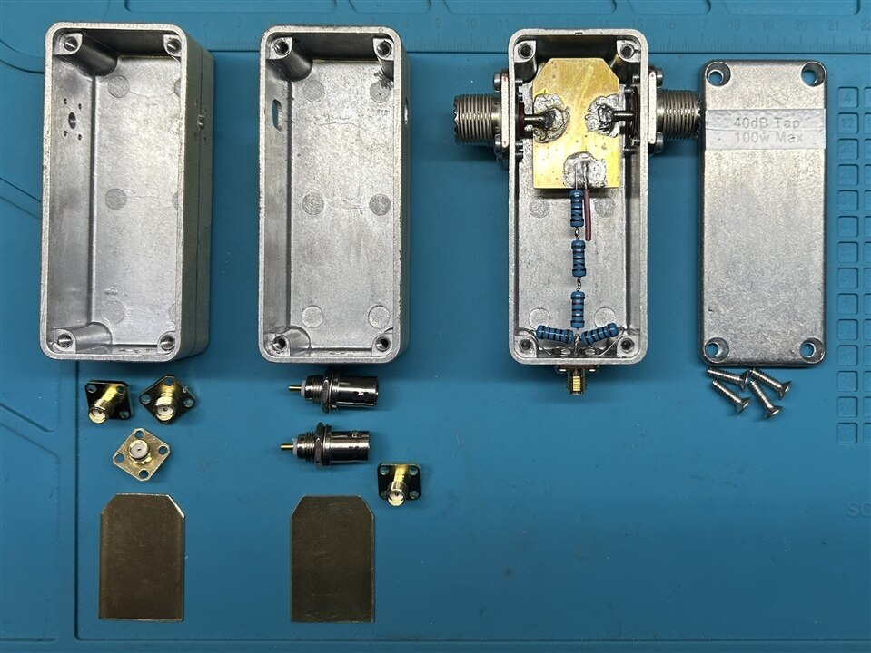
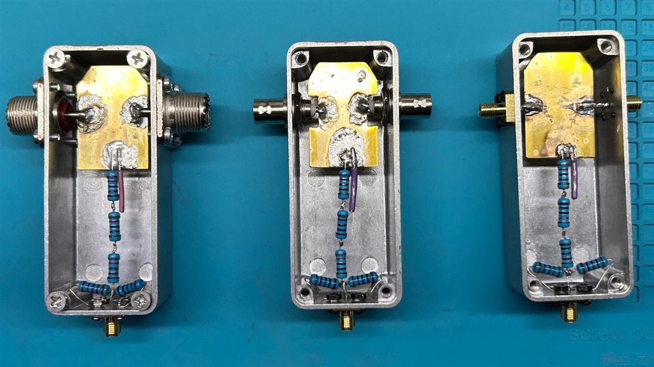
The purple wire is a gimmick capacitor and is supposed to improve performance at higher frequencies (>500MHz).
Pre-soldering the brass plate worked better than just buffing the plate and trying to solder on it while in place.
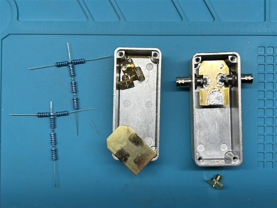
For the BNC version, the brass plate needed to be notched. I used a hand nibbler for that.
For the SMA version, connecting to the brass plate proved to be quite a chore. I used a piece of solid #14 to bridge the gap between SMA center pins. Once they were finally secure, I cut out the middle so the signal would flow through the brass plate. Soldering to the SMA connectors was by far the most difficult aspect of the project.
For the end SMA connector, I used longer mounting screws so I could secure the two 100 ohm resistors to chassis ground. Wrap the resistor tail around the protruding screw and secure with a nut. This proved to be quite handy.
Performance
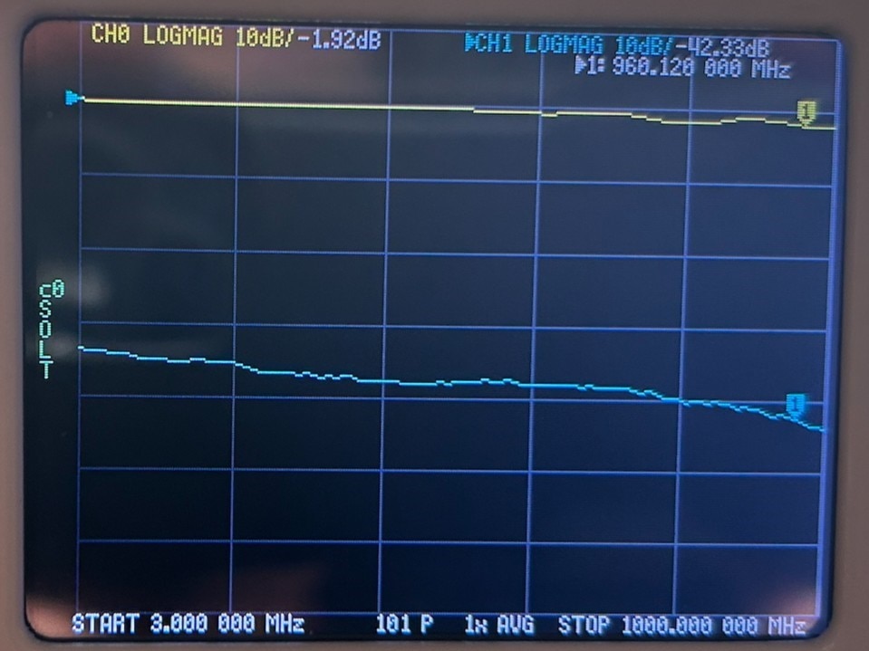
So how do they work? I give them a "Good" grade. According to my NanoVNA, they start at about 33dB of attenuation at 3MHZ. Since I really don't plan to blast 100 watts of power through these, I should be fine. The span depicted below is from 3 MHz to 1 GHz, although the article said that the tap was good only to about 500MHz. I could always try lengthening the gimmick capacitor.
SO-239 Version
BNC Version
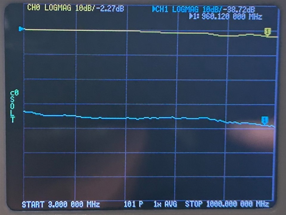
SMA Version

Conclusion
Again, soldering to the SMA bulkhead connectors was by far the most challenging aspect of this project. Truth be told, this was probably why I didn't complete the BNC and SMA versions until now. If I had to do it over again, I would try to use 22-26 AWG butt splice connectors to bridge between the center pin of the SMA connector and the plate or resistors. I would also not connect the two 100 ohm resistors until after the center run is soldered in place. Last build tip: Use way more wire than you need for the gimmick capacitor. You'll need some to hold on to while soldering. Once it's soldered in place, then trim to length
There are now less random pieces parts laying about on the workbench and a couple of more pieces of test gear on the shelf. If nothing else, my workbench is looking better than it has in months. Now if I could only figure out why I bought those 4 MHz TCXO's...

.
Top Comments