


A 3D printing of an assembly to hold the Breakout was one of my first forays into this type of printing. A new printer, learning the set up, discovering the software and applications made getting the tvscreen design finished a challenge. The drawing is a pdf. It is all I can find of files from creating a model in FreeCAD.

I only have the .stl and .gcode files and none of the native files for FreeCAD of the model. This exemplifies not knowing what you don’t know. I since have created a process for directories and files for 3D models that I develop. Hopefully I don't design a model again and never save the work effort.
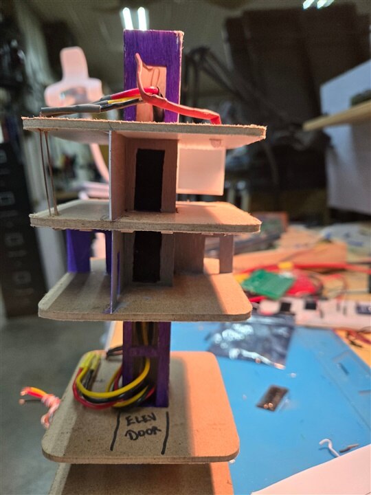
| {gallery}Looking at the tower floors |
|---|
|
The white box is screen one floor down from the top |
|
walls divide floor space |
|
not all floor are open for display |
|
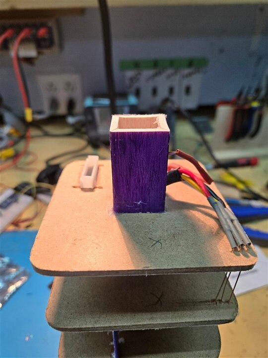
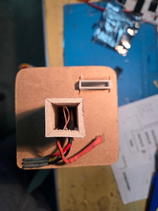
The empty space is for the Pi 2 |
|
the breakout fits into the slot of the box |
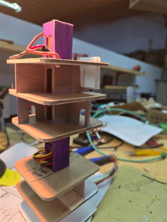

The initial plan positioned the Raspberry Pi’s Breakout connections for bottom entry. The television would be a floor model. Design of open floors (i.e. floors that are visible) didn’t permit this. The Pi is on the floor above the tvscreen animation floor. The 3D model simulates a room’s viewing screen. I'm told furniture with figures sitting and figure standing will fill out the floor.
A Raspberry Pi Zero is the microcontroller used to feed the Breakout. The hardware version is 1.3 dated 2015. I acquired the hardware long before the Breakout. I never had a use for it until now. Seven connections pair the two devices.

A 3D model from Thingiverse 3D printing repository was used to print a Raspberry Pi Zero case.
The DC power for the Pi originates from a 20,000mAh power pack on a floor lower down the tower structure. I'm currently testing how long the Pi2 and Breakout will run on the supply.
The first operating system (O/S) I loaded was Raspberry Pi OS Lite System: 64-bit Debian version: 12 (bookworm). I soon found that only the Pi Zero 2 supports 64 bit. My old hardware would not cut more bits. I change to Raspberry Pi OS Lite System: 32-bit Debian version: 12 (bookworm). After a software update and upgrade; the Pi was ready to code.
In reality, I used a different Raspberry Pi to load the O/S and develop the code. The hardware version of the Pi Zero had no networking capabilities. You soon discover updates and upgrades are impossible to do on hardware that is network neutered. Developing the project on Pi4 hardware, having more horsepower and networking capabilities, made it easier.
I took a video of the top level of the tower. Magic hands are at work to separate the structure. The complete tower is divided into three tiers. The video is of the top tier.
There is an outer shell that encases a floor insert. The outer shell will have most windows blacked out. Only those floors for display are visible.The outer shell has flexible LED lighting strips on the edges. There is a cell tower animation (no shown) not shown. You can see a connection at the top to support this animation. Two tiers of the tower have this LED lighting we hope to use for a lighting strobe animation.
The outer shell contains connections for different animations, as does the floor insert. The floor insert has an elevator shaft up the middle. The moving elevator I described in the last post is on a tier lower down. The elevators on this tier are static and just have lights and open doors. The elevator shaft doubles as the cable conduit. Floors that are open for display have more details. Walls, floor covering and lighting are currently being worked on. Programming LED strings are on some floors, allowing variable room lighting.
Except for the Pi 2 on the very top floor to animate the television the other microconfrollers and microcomputers are in the level below the ground level floor.
