The Project14 program manager(s) have put forth yet another exciting monthly project theme, this one is for all of us spy nerds. I did struggle to think of a project that would be worthy of the ‘Ultimate Spy Nerd’ crown. I had contemplated trying to prototype a laser microphone (https://en.wikipedia.org/wiki/Laser_microphone) which uses optical interferometry to measure the vibrations of objects in the vicinity of the sound emitter and then be converted into an equivalent audio signal. So, one can remotely monitor a bag of chips to learn all the latest spy gossip. That being said, I don’t have the optics for a laser Interferometry laying around in a box. So, I have instead decided to pursue a long-range laser communicator.
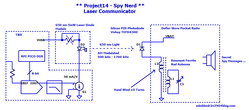
The Laser Communicator allows a spy to stay off the LF to UHF air waves while still communicating with their spy colleagues at long distances, provided there is line of sight.
Even if this isn’t This is the ultimate spy gadget for a spy nerd. It has been a lot of fun to building and testing this 'spy tech'. Playing with this kit reminds of playing with walkie talkies as a child, only now with lasers!
Proof of Concept
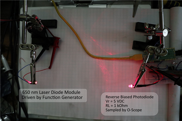
I am hoping to amplitude modulate the laser diode at the same carrier frequency used in mediumwave radio. So hopefully, all I need to do for the receiver side, is to add a photodiode coupled to the ferrite rod antenna. All of this rests on achieving a system bandwidth greater than the desired carrier frequency. So, I setup the laser diode and photodiode on my precision optical bench and did a quick test.
Here I am driving the laser diode module with a 1Vpp sinewave with a 4 VDC offset. Here are the results of sweeping the frequency from 100 kHz to 1200 kHz,
While this isn’t an overly scientific test, it does show I am on the right track. I think I have a pretty good chance of success with the electronics. I don’t know how well I am going to be able to test this over a 20 km optical path, but I think across a field should be quite manageable.
Receiver
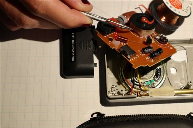
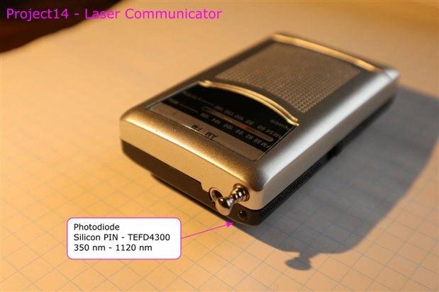
I was able to find a low-cost pocket radio with a resonant ferrite rod antenna from a local hobby shop. I had hoped to source the radio at the Dollar store, however there was no pocket radios to be found on the store’s shelves. I had also hoped the radio would have one end of the ferrite rod antenna coil grounded. So, I could directly attach the photodiode to LC tank this would provide DC bias to maintain the photodiode operating in photoconductive mode and reject any optical signal not near the resonant frequency of the LC tank. The radio I sourced did not have one end of the ferrite rod antenna grounded. Before I even knew if this was going to be the case, I received a brilliant suggestion from member shbaz to wind a secondary receive coil on the ferrite rod. This turned out to be an excellent solution. So, I hand wound 10 turns of 34 AWG enamel wire around ferrite rod, which operates as coupled inductor to the main resonant antenna winding. A TEFD4300 Silicon PIN Photodiode https://www.vishay.com/docs/83471/tefd4300.pdf, was then solder reverse biased to the newly added secondary receive coil.
For the stealthy spy look, I drilled a 7/64” hole near the telescoping antenna and forcefully slide the T1 photodiode into place. After making these modifications to the pocket radio, we now have a laser communicator receiver suitable for any spy nerd.
Transmitter
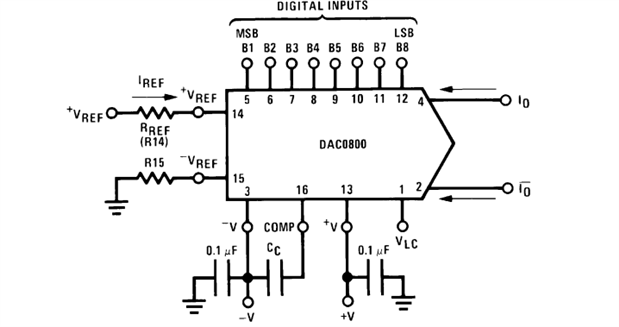
I am going to run a DDS on the 2nd core of a RPI Pico and then AM modulate the carrier by simply using a multiplying DAC (DAC0800).https://www.ti.com/lit/ds/symlink/dac0800.pdf
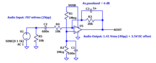
Audio Input
Amplitude Modulation
I Implemented amplitude modulation by using the audio input to derive the reference current for the DAC0800 (single quadrant multiplying DAC)
The audio source volume/level then defines the AM modulation index. Here I am adjusting the playback volume from minimum to maximum which eventually results in clipping:
DDS - Sample Clock
For this project, I am going to use a PIO state machine on the Rp2040 to define the DDS sample clock. To instantiate an 8-bit parallel FIFO state machine in uPython one can make use of the following python code:
# 8-bit parallel transmit FIFO
@rp2.asm_pio(out_shiftdir=1, autopull=True, pull_thresh=8, out_init=([PIO.OUT_LOW]*8),fifo_join=PIO.JOIN_TX)
def ddspio():
    wrap_target()
    out(pins, 8)
    wrap()

# Create a PIO StateMachine with the ddspio program, outputting on pins gp0 - gp7
sm = rp2.StateMachine(0, ddspio, freq=25_000_000,  out_base=Pin(0))
sm.active(0)
# load FIFO with some interesting data
for i in range(8):
   sm.put(i)

print('TX0 FIFO Count: {}'.format(mem32[0x50200000+0xc]))
sm.active(1)
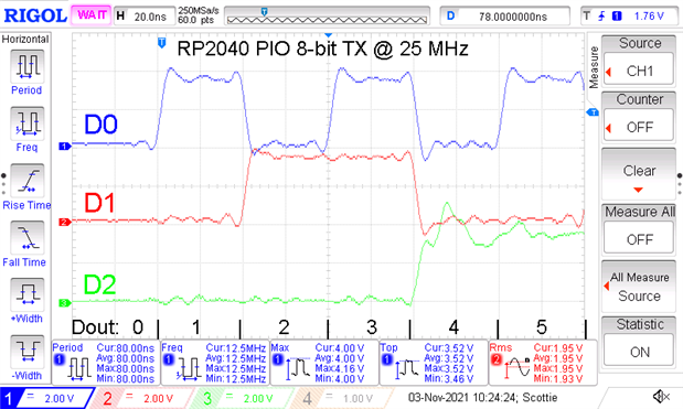
Which will output binary codes 0 through 7 across GPIO pins 0 through 7, with a sample clock of 25 MHz
DDS - Assembly Template
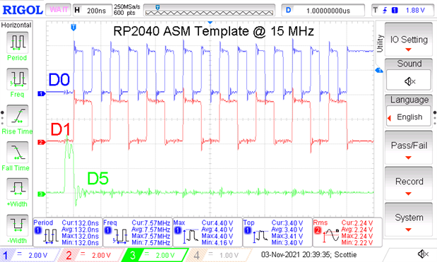
This looks simple now, but it took along time to get to that point from hard lessons in past projects. Here I am counting down from 32 and during each loop iteration writing the counter value (r1) to the PIO TX0 FIFO.
@micropython.asm_thumb
def ddsasm(r0):
    ldr(r1,[r0,0])
    ldr(r2,[r0,4]) # r2 = addr PIO_BASE
    label(START)
    ldr(r3,[r2,0x0C]) # check to see if TX0 FIFO is full
    cmp(r3,8)
    beq(START)
    str(r1,[r2,0x10])
    sub(r1,1)
    cmp(r1,0)
    bne(START)

fptr = array.array('i',[ 32, 0x50200000, addressof(LUT), 3])
ddsasm(fptr)
I also had to slow down the PIO state machine to 15 MHz as this assembly loop takes more than 5 clock cycles. Also note, in this basic example the compare and branch not-equal falls through on 0, so a 0 is never written to the TX FIFO.
DDS - Sine Look Up Table
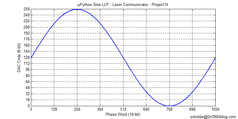
It's moments like this where uPython really presents a warm charm. In the past I would have hardcoded a lookup table as an array, but it's a one liner in python. So, during initialization I instantiate a sine lookup table in memory by:
# Sine LUT 10-bit phase input to 8-bit DAC code
ILUT = [ int(127.5*math.sin(x*2*math.pi/1024) + 127.5) for x in range(1024)]
LUT = bytearray(ILUT)
del ILUT
I exported the LUT to double check it was correct, this was as simple as:
f = open('lut.dat','wb')
f.write(LUT)
f.close()
Here is the LUT plotted for all input phase codes:
DDS - NCO
Just a sneak peak before I consider this ready for primetime:
    add(r4,r4,r1) # Add the TUNEING word to the phase accumulator
    lsr(r5,r4,22) # slice the upper 10 bits of the ACCUM into r5
    add(r5,r3,r5) # add the LUT address to r5
    ldrb(r6,[r5,0]) # r6 = LUT[ACCUM<31:22>]
    str(r6,[r2,0x10]) #store in sio memory 1 cycle
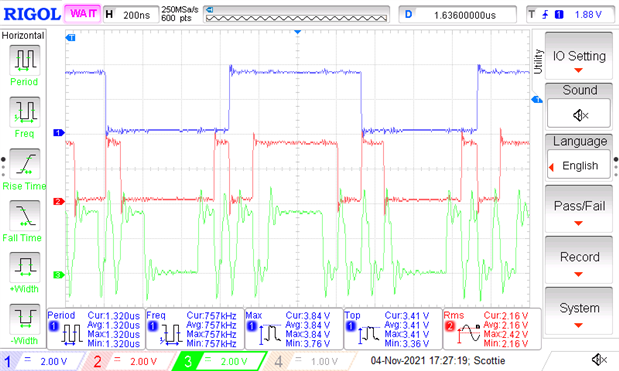
We are definitely getting close:
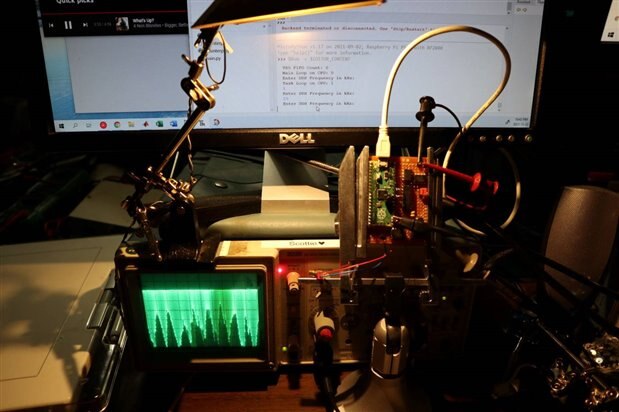
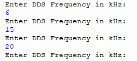
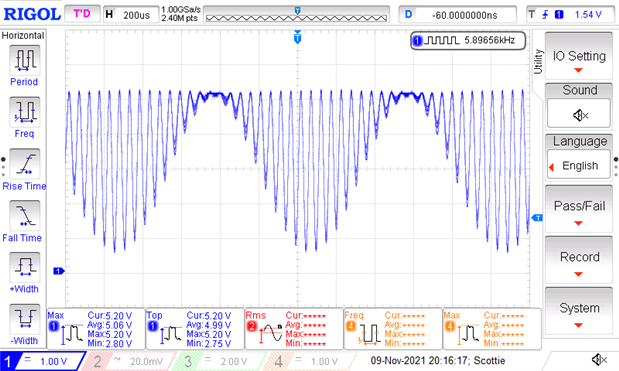
Here I am just using a 1kHz tone generated from my function generator as the audio input and running the DDS at 20 kHz.
DDS - Reconstruction Filter
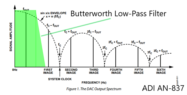
The DDS is operating with a sample rate of 22.5 MHz, so I have arbitrarily chosen my reconstruction filter to have a cut-off frequency of 10 MHz. Depending on the level of attenuation achieved in the filter's stop band, the reconstruction filter will attenuate the unwanted aliased sampling images.
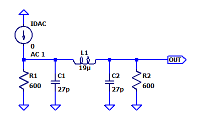
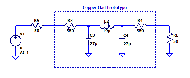
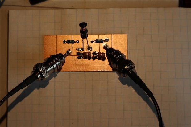
I prototyped a 3rd order Butterworth filter designed for a source and load impedance of 600 Ohms.
In order to measure the frequency response of the filter with my NanoVNA, I needed to increase the effective source and load resistance as seen by the filter.
The series inductor was sourced from 270 uH inductor with approximately 70% of the turns removed (inductance scales with the square of the number of turns). The two shunt capacitors each consisted of a 20 pF and 10 pF capacitor in parallel.
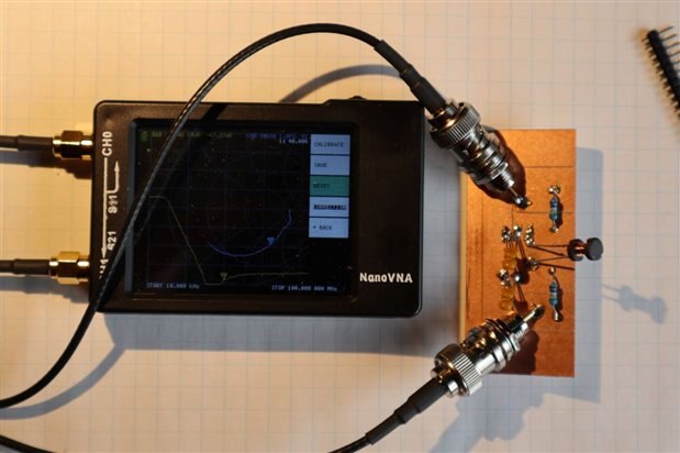
To measure the frequency response of the filter I make a S21 measurement with my NanoVNA:
Note because I added series resistors to achieve the 600 ohm source/load impedance there will be a baseline insertion loss of -22 dB.
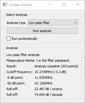
Not too bad for a quick little prototype. You can see the inductor self-resonate at approximately 33 MHz, which limits the high-frequency stop band attenuation. The Nano-Savers filter analysis tool reported a cut-off frequency of 10.3 MHz.
DDS – NCO V2.0
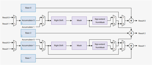
Some of the DDS calculations and bit operations can be implemented on one of the RP2040’s Interpolators located in the single-cycle IO block.
I was able to implement some of the DDS core operations, namely, incrementing the phase accumulator and generating the DAC lookup table element address.
ACUM0 : Phase Accumulator
BASE0: NCO Tuning Word
BASE2: LUT Base Address
Upon reading from one of the POP registers, in this case POP_RESULT2, the accumulator registers are clocked and new DDS sample is calculated and available on the next read of the result2 register. After making use of the interpolator to offload some of the DDS calculations I was able to achieve a sample rate of 30 MSa/s. A sample rate of 30 MSa/s is really pushing the vintage through-hole DAC0800 to its limits, however there are modern surface mount DACs available. If one doesn’t need amplitude modulation, you can use a resistor R-2R ladder DAC connected directly to the RP2040’s GPIO pins. Ultimately, I was able to reduce the following instructions:
    add(r4,r4,r1) # Add the TUNEING word to the phase accumulator
    lsr(r5,r4,22) # slice the upper 10 bits of the ACCUM into r5
    add(r5,r3,r5) # add the LUT address to r5
To a single register load from the interpolator's result2 register:
ldr(r5,[r4,0]) # Read Interp Result
Essential Bill of Materials
| Component | Newark PN |
|---|---|
| RPi Pico | Raspberry Pi Pico, Microcontroller Board, RP2040, 32 bit, 2MB Flash, ARM Cortex-M0+Raspberry Pi Pico, Microcontroller Board, RP2040, 32 bit, 2MB Flash, ARM Cortex-M0+ |
| DAC0800 | IC, 8BIT DAC, PARALLEL, 16DIPIC, 8BIT DAC, PARALLEL, 16DIP |
| MCP601 | Operational Amplifier, Single, 2.8 MHz, DIP, 8Operational Amplifier, Single, 2.8 MHz, DIP, 8 |
| 7660 Charge Pump | Charge Pump Voltage Converter, 1.5V to 12V in, -12V to -1.5V/45 mA out, DIP-8Charge Pump Voltage Converter, 1.5V to 12V in, -12V to -1.5V/45 mA out, DIP-8 |
650 nm Laser Diode | - |
| Pocket Radio | - |
| TEFD4300 Photodiode | Photodiode, 20 °, 150 pA, 950 nm, T-1 (3mm)Photodiode, 20 °, 150 pA, 950 nm, T-1 (3mm) |
Demo
Thanks for reading! Comments and suggestions are always welcome  .
.




Top Comments
-

scottiebabe
-
Cancel
-
Vote Up
+1
Vote Down
-
-
Sign in to reply
-
More
-
Cancel
Comment-

scottiebabe
-
Cancel
-
Vote Up
+1
Vote Down
-
-
Sign in to reply
-
More
-
Cancel
Children