Introduction
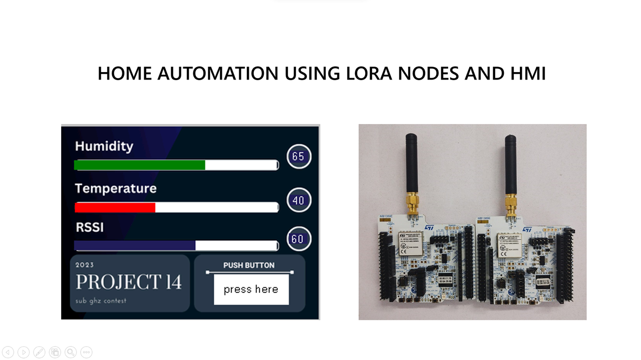
In the previous blogs, I have run the example codes that are already available as a part of BSP package. As a finishing blog, I have decided to create a wireless offline home automation device that has an HMI display interfaced to it.
Source code
Hosted in my 
Test
- Transmit the temperature and humidity data from sensor node to responder node.
- Parse the incoming data
- Display the resulting information along with RSSI on the display
- Create a toggle button to send output signal to sensor node.
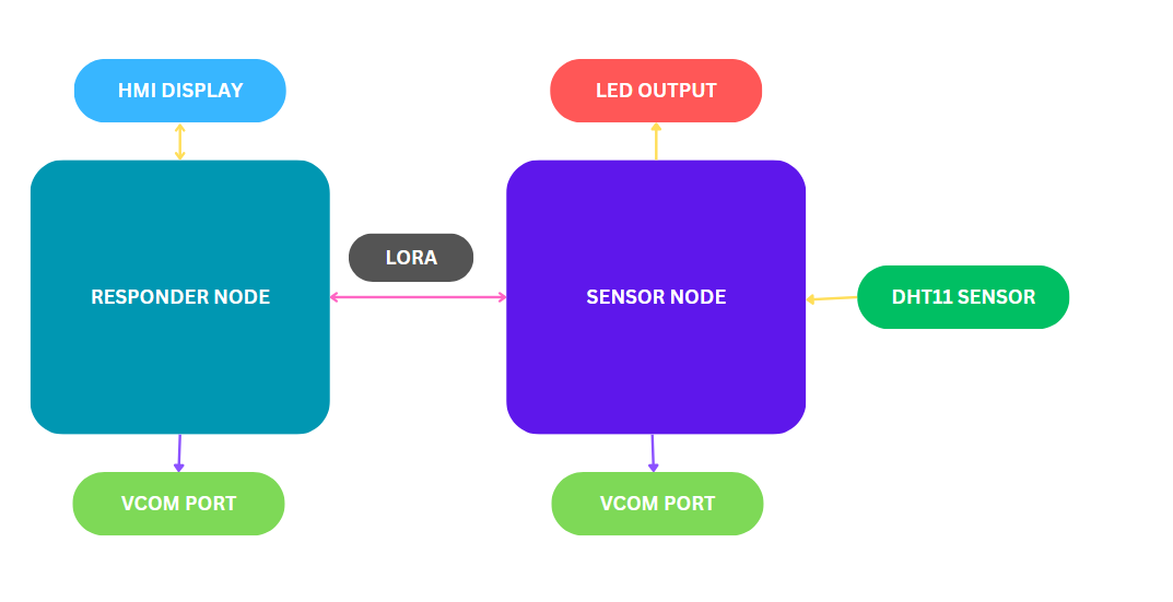
Sensor node Setup
- Nucleo-WLxx board
- DHT11 sensor. I have simulated the sensor for a simper proof of concept.
- One output device. Could be a relay or any simple GPIO based output. I have selected to use the available LED in Nucleo board
Responder node Setup
- Nucleo-WLxx board
- Nextion HMI display
Block diagram

Sensor node Code explanation
Comment the RECEIVER_NODE definition to enable sensor node.

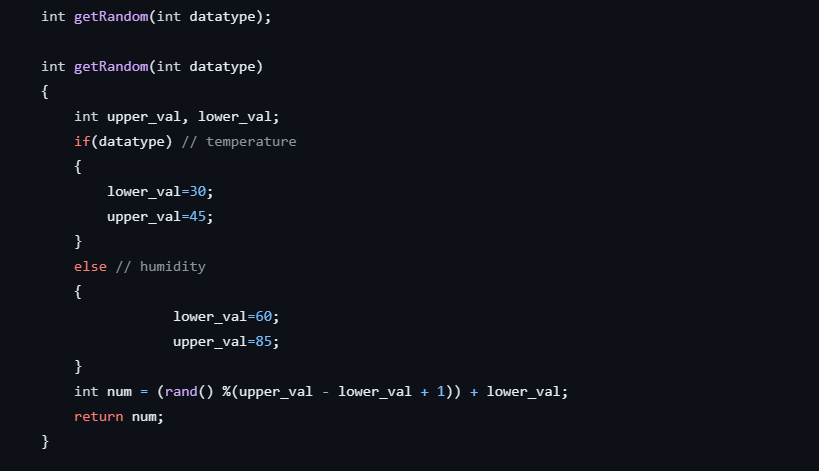
To avoid overshooting of simulated values, range was set to get the random value between upper and lower bound. Adjust the upper/lower values of temperature and humidity sensor as per your preferred range. For temperature (datatype = 1), upper and lower values are set as 45 and 30 respectively. For temperature (datatype = 0), upper and lower values are set as 85 and 60 respectively.

Get the value of simulated data and copy it into CONFIG_FILE struct instance config. On PingPong_Process function, payload will be transmitted on RX state.

On OnRxDone function, add GPIO toggle function.

Responder node Code explanation
Enable the RECEIVER_NODE to activate responder node
On OnRxDone function, copy the received payload to a temporary CONFIG_FILE struct instance.

Parse the value stored and print it over the vcom.
Send the data to display by calling sendCommand(int, int).

On receiving data from sensor node, send the “PING” message to sensor node to toggle the current state of LED through PingPong_Process function.

Issues faced and mitigation
- UART1 connected to display does not work when LORA application is running. When I disable the main application and run the test code for display checking, UART works and the HMI values change.
- The press button on display was initially designed to send “PING” data to sensor node whenever pressed, as the UART does not work, message from display is not received at controller. So to toggle LED, whenever responder receives LORA message it will send “PING message”
- Yet to include the fix to enable the UART along with main example.
Outcome
A simple home automation device was created and the working was tested.
ToDo
- Enable the UART communication between responder and display.
- Connect the LORA node to gateway using LORA gateway device or wifi router using host device.
- Connect multiple LORA and provide an unified way to display them in HMI

