Thanks to the SubGHz contest - RF has been on my radar to explore for a while now and using STM32WL is where I got started. The radio drivers and middlewares are quite complex coming to these systems, but the getting started example helped me here.
This blog explains my activity building a basic door-lock system prototype using two STM32WL devices one acting as a node put near the door and the other the concentrator or remote device within the radio vicinity(range test activity is to be done next). Thanks to element14 for shipping out a pair of STM32WL55JC1 Nucleo-64 boards for participating in this contest. Here we go:
1. Getting Started
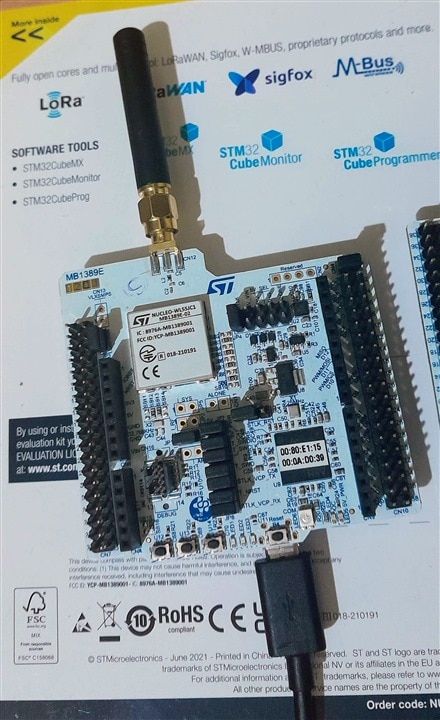
Downloading the STM32CubeWL pack is all that is needed to get the skeleton in place which provides Middlewares, Drivers, and Example Programs all documented well to an extent. The examples for usage of each peripheral are helpful in understanding their setup, configuration and testing out features on top of which application programs can be built. I am using a C1 version of this board - EU/US/APAC 868/915/923 MHz and another is C2 which is CN 433/470 MHz.
2. Example Programs
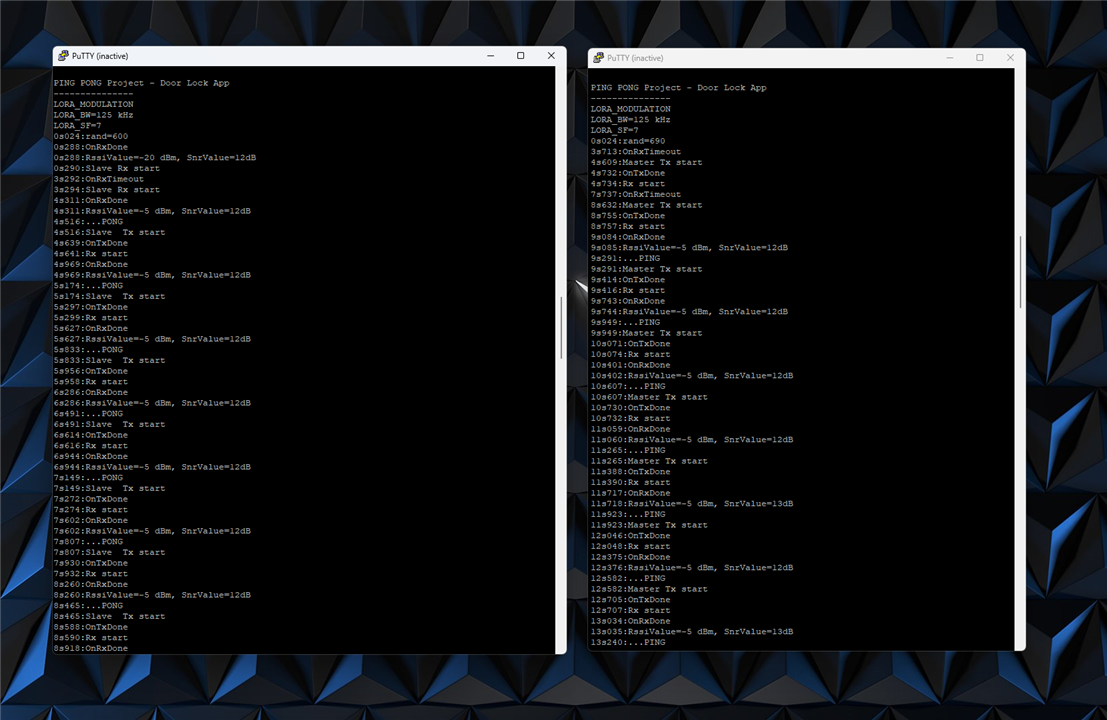
Running ping pong example where the master device pings and node gives a response through a pong. Another demo is sensor and concentrator where the concentrator collects the data from the sensor.

3. Door Lock App Plan
The idea of this project is to have a ping-pong type of instance where the remote device sends a message to open the door to a node in the vicinity upon a user button press. The node receives and sends the new door status after the reception of the message. The remote will now know the current state of the door and be ready for further commands. While the node also controls a buzzer and solenoid valve linking to a door latch.
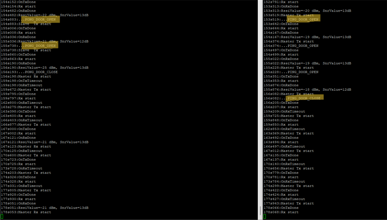
PING_DOOR_OPEN / PING_DOOR_CLOSE
PONG_DOOR_OPEN / PONG_DOOR_CLOSE
4. Implementation
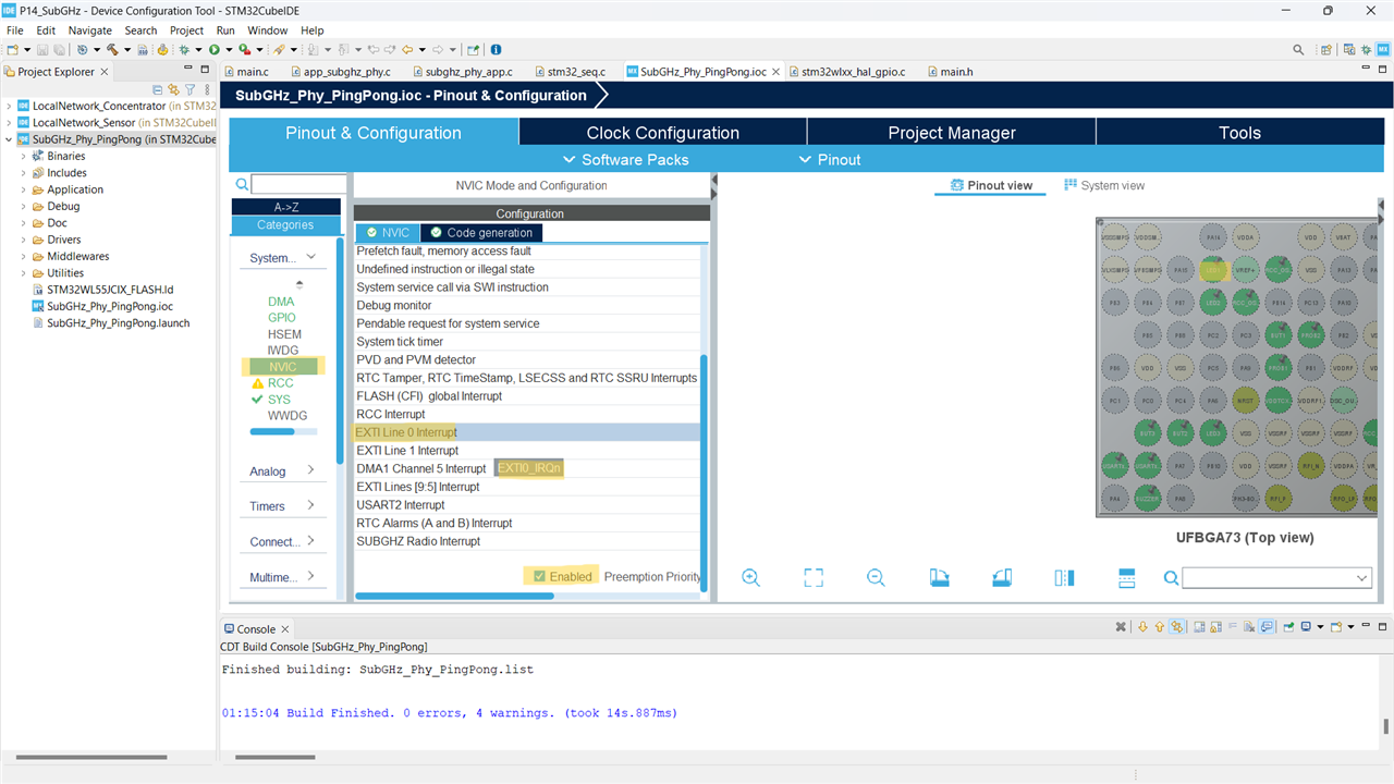
Enabling interrupts in STM32CubeMX .ioc file:
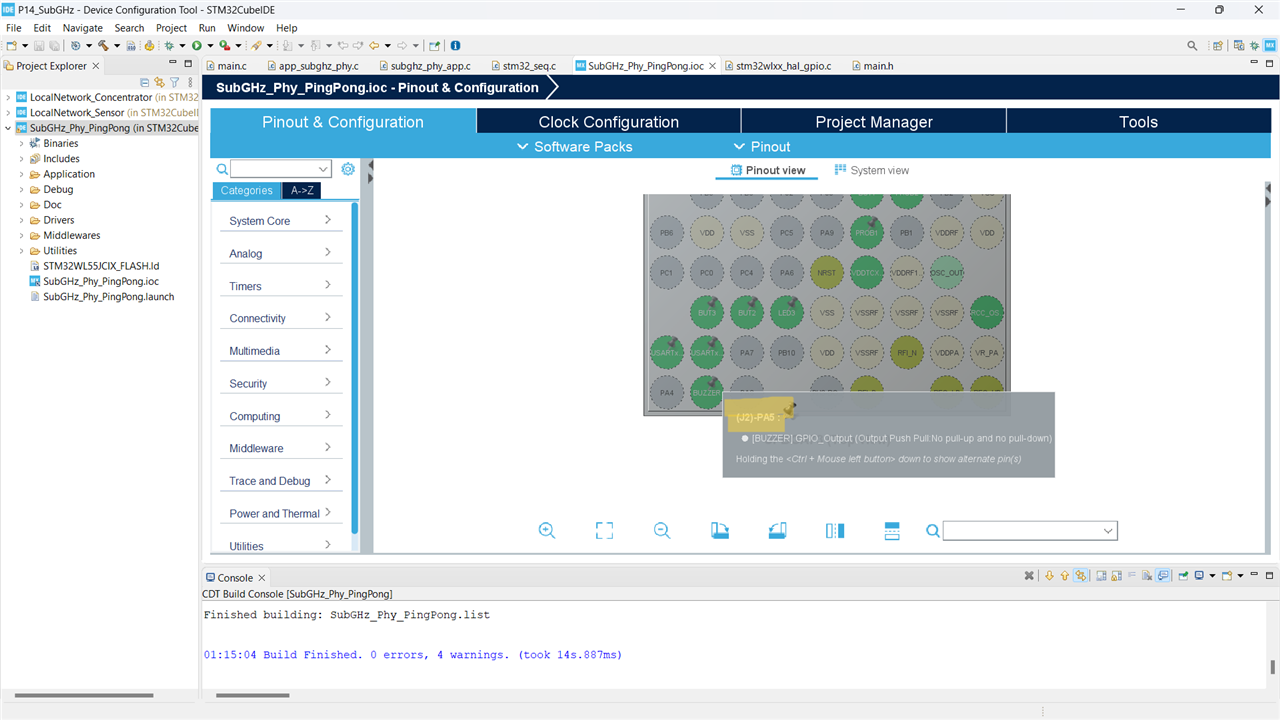
Adding additional IO pin for the buzzer:
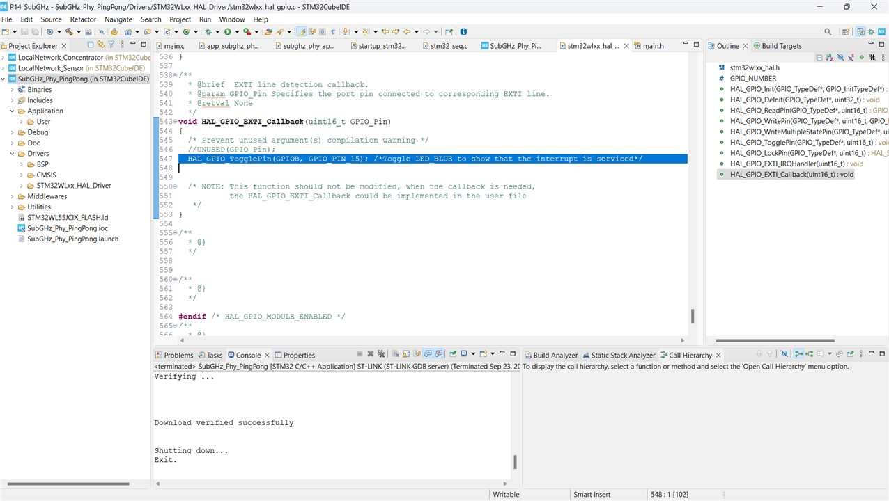
ISR:
Demo:
Here, on a button press in the remote device(indicated by BLUE LED and the node indicates remote's button press with GREEN LED), a ping is sent to the node which pongs the status. The link is established between them in prior and the blue LED in the node device indicates that the device is activated to do the task of opening/closing the door. On the remote side, based on if the door is open/closed, the BLUE LED status changes while node shows it by GREEN LED. A buzzer beeps for an instant of the door left open.
5. References and Next steps
Further, I am exploring encryption blocks and LPUART in this module. The activity of running RF range tests and power consumption at different phases of operation will be added next. Let me know what you think and if you have to build ideas with this board!
