element14 Community
element14 Community
    Register Log In
  • Site
  • Search
  • Log In Register
  • Community Hub
    Community Hub
    • What's New on element14
    • Feedback and Support
    • Benefits of Membership
    • Personal Blogs
    • Members Area
    • Achievement Levels
  • Learn
    Learn
    • Ask an Expert
    • eBooks
    • element14 presents
    • Learning Center
    • Tech Spotlight
    • STEM Academy
    • Webinars, Training and Events
    • Learning Groups
  • Technologies
    Technologies
    • 3D Printing
    • FPGA
    • Industrial Automation
    • Internet of Things
    • Power & Energy
    • Sensors
    • Technology Groups
  • Challenges & Projects
    Challenges & Projects
    • Design Challenges
    • element14 presents Projects
    • Project14
    • Arduino Projects
    • Raspberry Pi Projects
    • Project Groups
  • Products
    Products
    • Arduino
    • Avnet Boards Community
    • Dev Tools
    • Manufacturers
    • Multicomp Pro
    • Product Groups
    • Raspberry Pi
    • RoadTests & Reviews
  • Store
    Store
    • Visit Your Store
    • Choose another store...
      • Europe
      •  Austria (German)
      •  Belgium (Dutch, French)
      •  Bulgaria (Bulgarian)
      •  Czech Republic (Czech)
      •  Denmark (Danish)
      •  Estonia (Estonian)
      •  Finland (Finnish)
      •  France (French)
      •  Germany (German)
      •  Hungary (Hungarian)
      •  Ireland
      •  Israel
      •  Italy (Italian)
      •  Latvia (Latvian)
      •  
      •  Lithuania (Lithuanian)
      •  Netherlands (Dutch)
      •  Norway (Norwegian)
      •  Poland (Polish)
      •  Portugal (Portuguese)
      •  Romania (Romanian)
      •  Russia (Russian)
      •  Slovakia (Slovak)
      •  Slovenia (Slovenian)
      •  Spain (Spanish)
      •  Sweden (Swedish)
      •  Switzerland(German, French)
      •  Turkey (Turkish)
      •  United Kingdom
      • Asia Pacific
      •  Australia
      •  China
      •  Hong Kong
      •  India
      •  Korea (Korean)
      •  Malaysia
      •  New Zealand
      •  Philippines
      •  Singapore
      •  Taiwan
      •  Thailand (Thai)
      • Americas
      •  Brazil (Portuguese)
      •  Canada
      •  Mexico (Spanish)
      •  United States
      Can't find the country/region you're looking for? Visit our export site or find a local distributor.
  • Translate
  • Profile
  • Settings
Test Instrumentation
  • Challenges & Projects
  • Project14
  • Test Instrumentation
  • More
  • Cancel
Test Instrumentation
Blog Automated Cable Test System .. part 2
  • Blog
  • Forum
  • Documents
  • Events
  • Polls
  • Files
  • Members
  • Mentions
  • Sub-Groups
  • Tags
  • More
  • Cancel
  • New
Test Instrumentation requires membership for participation - click to join
  • Share
  • More
  • Cancel
Group Actions
  • Group RSS
  • More
  • Cancel
Engagement
  • Author Author: phoenixcomm
  • Date Created: 24 Oct 2018 9:55 PM Date Created
  • Views 2682 views
  • Likes 3 likes
  • Comments 6 comments
  • nexgen
  • semi-automated
  • vme
  • cable tester
  • diy electronics
  • diytestinstruch
  • diy test equipment
Related
Recommended

Automated Cable Test System .. part 2

phoenixcomm
phoenixcomm
24 Oct 2018

Last night I woke up about 4 AM and realized that I don't have to use any Arduino(s) for the Cable Tester. image  I remembered that I had picked up a VME chassis with a bunch of Rotec I/O cards. The final configuration will  be 256 channels (half input and half output)  So here what I'm going to do.

Parts:image

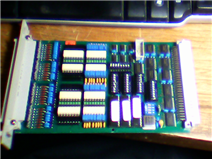
  • 32 channel Output Card(s) DIG 32-Ok (I have 4 of them)
  • 32 channel Input Card(s) DIG 32-IS (need 4 and I have 6 of them)
  • Interface Cables RTC-K-049/4M (need 8 and I have 10 of them.)
  • VME CPU w/ Ethernet
  • Hard Drive Interface
  • VME Chassis & Power Supply
  • Linux Box for GUI etc.

Problems: image

  • Rotec Gmbh is in Germany which is an early call for me so I have to call before 7 AM (about 2 PM in the afternoon), hopefully, they will have the documents I will be looking for. The other problem is my German well sucks. image
  • I will have to pull apart my lab to get at the large VME rack at the bottom of the stack. Hopefully, it still powers up.
  • Then I have to find a CPU that's not too old so I can run Linux on it.
  • VME/SCSI Adapter a nice Motorola MVME-327A hda brand new in the box.image
  • I need to find an MVME-717 SCSI Transition Module. As it so happens I can just run a 50 pin cable from P2 on MVME-327A to the hard drive directly. As per paragraph 5.2 in dah manual. (aren't they great)image
  • After all that I just need a hard drive. And then I write some software.

* Please Note that some of the Problems are in Red or Not done and when Green they are done.


~~ Cris H. image

Stay Tuned, More to Come!


NOTES & ADDENDUM:

  • Just found a VMIC 7648 which is a 32 bit Intel P3 with 512Mb of memory, Ethernet, USB, VGA, but no hda on the SBC. (more problems)
  • Before I try and recover the large chassis I can test the CPU and HDA combo in a small 6 slot desktop chassis.


Back to the Monthly Index
image

  • Sign in to reply

Top Comments

  • inghernandez
    inghernandez over 6 years ago +1
    it´s a good job, congratulations
  • phoenixcomm
    phoenixcomm over 6 years ago in reply to inghernandez +1
    thank you but the project was never completed. there were too many parts both the microbit and the Arduino where just distractions. I never got Rotec to answer 4 emails or phone calls ( they heard English…
  • mike-0rc
    mike-0rc over 5 years ago in reply to phoenixcomm +1
    I'm currently working on some test equipment with adapter PCB's using a PIC32 which is a 144 pin chip, it has the ability to use the pins as general I/O with weak pull ups internal to the chip, there is…
  • phoenixcomm
    phoenixcomm over 5 years ago in reply to mike-0rc

    I work with large count mill circular connectors. So what I was going to do was this:

    2 x 50 pins (ribbon connector) one for input the other for outputs.

    for self-test put in a 50 pin jumper cable.

    I also wanted two  pairs of DB-25, male-male and female-female

    as well as a pair of RJ45 connectors.

    the 50pin, a male DB-25, a female DB25, and the RJ45 are all wired pin 1 - 1, etc.


    Then I need to build a test adapter ie 50-pin to the circular connector.  

    then by using my VME I/O cards, I can do almost the same thing.


    But the problem is that no two cables are ever the same! (sort of like the Tower of Babel"

    The only thing that my simulator has going for it is that all of my slave interface cables terminate in multiple DB-25Fs with G-d only knows what's on the other end.

    This means that there is a lot of time spent with my Fluke Multimeter (Diode check) and maybe a diagram or a pin-out. image


    left side is outputs

    right side is inputs


    -------------------50pin--------------------     -------------------50pin--------------------

    -----------DB25F------DB25F-----------     -----------DB25F----

    -----------DB25M-----DB25M------------    ----DB25M-----------

    ---RJ45---                                               ---RJ45--- 


    the reason that there are two DB25F & DB25M on the output side most of my interfaces have two DB25M coming from the radio or whatever.

    • Cancel
    • Vote Up 0 Vote Down
    • Sign in to reply
    • More
    • Cancel
  • mike-0rc
    mike-0rc over 5 years ago in reply to phoenixcomm

    I'm currently working on some test equipment with adapter PCB's using a PIC32 which is a 144 pin chip, it has the ability to use the pins as general I/O with weak pull ups internal to the chip, there is a dedicated USB 2 port for debugging and for accessing the results that is easy to implement using the harmony Microchip IDE program All free to use. The chip I am currently working with is the PIC32MZ2048EFH144 200Mhz version, And your code that you would use for your cable check would look something like this;


    uint_t16 CableSet_1 = 0; // this will create an unsigned int of 16 bit so you can test 16 wires.

    TRISA = 0xFE; // set the port (Can be any of the 16bit ports) to input except the wire being tested.

    char a = 0; create a char for running the for loop to check the wires in sequence.

    char b = 0; create a char for pointing at a

    WRU = 0xFF ; universal pull ups ~~~ you need to set these in the pin setup in MHC of the IDE...

    ### Main Program ###


    for (a=0;a<15;a++)

    {

         CableSet_1 = CableSet1_1 & PORTA; // copies the IO of Port A to the Int.

         TRISA = TRISA<<; // this should bit shift the output pin one to the left.

    }


    Sprintf(USB_TX_BUFFER,CableSet_1);

    USB_TX_TASK();

    CableSet_1 = 0;


    So the above should send a 0V down one wire at a time and then any shorts would pull the weak pull up voltage down to 0V and showing a short.

    You could link two ports together and then you can read the other end of a wire to check for continuity.


    You would need to fiddle a bit with the code to get it to do what you wanted but this is a good stating point.


    I have a more complex method for doing the same as this but this is the basic program that will check for shorts and continuity.


    Hope it helps, and if you need any more help let me know.


    Regards,

    Mike Clapham.

    • Cancel
    • Vote Up +1 Vote Down
    • Sign in to reply
    • More
    • Cancel
  • phoenixcomm
    phoenixcomm over 5 years ago in reply to mike-0rc

    Mike, Unfortunately, No.  As with my untimely move which is still going on, (now the unpacking phase), One of the problems that I have is that the German company who made the I/O cars, claims on their website that their customer service is in German and English, but whenever you say "Hello" they hang-up! Since these cards are VME cards every card has address space. And if I don't mess about with the current address, and write a simple walking test it should be a minor problem to find them. Since all the cards are on the VME bus I don't have to worry about timing issues, ie look at a data book for that.

    I wanted to have a generalized I/O cables most likely two 50 pin flat ribbon cables then all I do is build an adapter. I also wanted to have a pair(s) of DB-25F, DB-25M and two RJ-45's of course as well. So basically, from one of the 50 pin connectors pins 1-25 goes to one DB-25F, one DB-25M, and pins 1-8 goes to the RJ45. Therefore the 'test cable' would be a 50pin - 50pin cable.


    I am also undertaking a major rewrite of the Radio SubSystem Codebase from C to Java (which I have problems with (learning curve).

    • Cancel
    • Vote Up 0 Vote Down
    • Sign in to reply
    • More
    • Cancel
  • mike-0rc
    mike-0rc over 5 years ago in reply to phoenixcomm

    Did you finish this project?

    Back in 2011 I developed a device that checks multiple pins and then displays the results on an LCD screen, this was for checking to see if any pin was connected to any of the other pins and also to check for continuity between specific pins, We use them constantly at work and it had the added benefit of adjustable sensitivity (Purely by accident) by increasing the clock speed and later found that the charge/discharge of the pins were the cause. May be something like this could be used? It uses an internal pull up in the micro  and then drive one output low to see if any of the other pins are effected.


    Mike.

    • Cancel
    • Vote Up 0 Vote Down
    • Sign in to reply
    • More
    • Cancel
  • phoenixcomm
    phoenixcomm over 6 years ago in reply to inghernandez

    thank you but the project was never completed. there were too many parts both the microbit and the Arduino where just distractions.

    I never got Rotec to answer 4 emails or phone calls ( they heard English the just hung up!) the project will go forward with my small VME test rack until I can write my own drivers!

    My code base came from an open source project with running on an Arduino with a custom shield.  and ut could do 25x25 which is not what I want. You have to understand that some of my cables start with a 150 pin connector so I needed a "guided flying probe".

    One of my goals is to be able to use configuration files (maybe XML) or no configuration, ie plug one end in, and use the flying probe to build a wiring diagram and configuration file.

    In the configuration files, I can also include the connector parts list (manufacture & part number) as well as pin counts with labels.

    As DB-7, 9, 15, 25, 35, 50 are numbered 1 to n. But with the circular connectors, some are lettered which are not always consecutive and have upper and lower, and or underlined.

    • Cancel
    • Vote Up +1 Vote Down
    • Sign in to reply
    • More
    • Cancel
>
element14 Community

element14 is the first online community specifically for engineers. Connect with your peers and get expert answers to your questions.

  • Members
  • Learn
  • Technologies
  • Challenges & Projects
  • Products
  • Store
  • About Us
  • Feedback & Support
  • FAQs
  • Terms of Use
  • Privacy Policy
  • Legal and Copyright Notices
  • Sitemap
  • Cookies

An Avnet Company © 2025 Premier Farnell Limited. All Rights Reserved.

Premier Farnell Ltd, registered in England and Wales (no 00876412), registered office: Farnell House, Forge Lane, Leeds LS12 2NE.

ICP 备案号 10220084.

Follow element14

  • X
  • Facebook
  • linkedin
  • YouTube