Arduino or any other controller need TTL signal levels at input to count pulses and only work with square wave.
So what if we want to find out the frequency of sine ,triangular or low voltage square wave?
We can solve this problem with the help of comparator IC like lm339 which can operate down to 2V (Fig. 1) and also we can use separate power supply to power up the IC and use TTL voltage to pull up the output of comparator. (FIG. 2)
FIG. 1
FIG. 2
If we look at arduino UNO R3 specification we can find that it has 3 timers TMR0 (8-bit), TMR1 (16-bit) and TMR2 (8-bit) also shown in block diagram of ATmega 328P (FIG. 3). And Only TMR0 and TMR2 can be used as input.
| TIMER | Arduino IO - pin |
|---|---|
| TMR0 | IO - 4 (INPUT) IO - 5 & 6 (OUTPUT) |
| TMR1 | IO - 5 & 8 (INPUT) IO - 9 & 10 (OUTPUT) |
| TMR2 | IO - 3 & 11 (OUTPUT) |
We can use use either TMR0 or TMR1 as frequency Input. To choose the best option between these two timers we can opt TMR1 as input because it is 16-bit. And use other two timers in cascading to calculate elapsed time for better accuracy. (After editing TMR1 setting we cannot use millis and micro)
FIG. 3
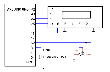
Connect the arduino UNO with 16x2 LCD as shown in FIG. 4.
FIG. 4
We can use TMR0 and TMR2 to generate 1 second time. To use both timer we have to physically link the output of TMR2 to TMR0. (IO - 3 to IO - 4). The Arduino record the no of pulses at TMR1 input (IO - 5) for 1 second, for each time if TMR1 overflow during 1 second record time the overF variable is incremented by 1. After recording number of pulses for 1 sec it calculate the frequency and time period of input signal.
#include <LiquidCrystal.h>

  byte overF=0;
  unsigned long freq;
  double period;

   // initialize the library with the numbers of the interface pins
  LiquidCrystal lcd(12, 11, A2, A3, A4, A5);

// the setup function runs once when you press reset or power the board
void setup() {

    lcd.begin(16, 2);   // set up the LCD's number of columns and rows:

    //4*250 = 1000 ms - timer0
    OCR0A = 249;
    TCCR0A = _BV(WGM00) | _BV(WGM01); // (Normal port operation, OC0A disconnected.)
    TCCR0B = _BV(WGM02) | _BV(CS02) | _BV(CS01);  //  Fast PWM mode, input T0 pin D4 (External clock source on T0 pin. Clock on falling edge.)

    //4 msec - timer2
    OCR2A =249;
    OCR2B = 125;
    TCCR2A = _BV(COM2B1) | _BV(COM2B0) | _BV(WGM21) | _BV(WGM20);  //output B in phase, fast PWM mode (Set OC0B on compare match, clear OC0B at BOTTOM, (inverting mode))
    TCCR2B = _BV(WGM22) | _BV(CS22) | _BV(CS21); // set prescaler to 256 and start the timer
    pinMode(3, OUTPUT);

    //  counter input T1 pin D5
    OCR1A = 32767;   //32768 counts
    TCCR1A = _BV(WGM10) | _BV(WGM11); //   Fast PWM Mode (Normal port operation, OC1A/OC1B disconnected)
    TCCR1B = _BV(WGM12) | _BV(WGM13) | _BV(CS12) | _BV(CS11); //input pin D5 (External clock source on T1 pin. Clock on falling edge.)

    lcd.setCursor(7, 0); // top middle
    lcd.print("hi");

}


  // the loop function runs over and over again forever
void loop() {

      //wait for 1-sec
    TIFR0= _BV(OCF0A);
    while(!(TIFR0 & (1<<OCF0A)));


    TIFR1 = _BV(OCF1A);    //reset TMR1 overflow flag
    OCR1A = 32767;
    TCNT1=0;
    overF=0;
    TIFR0= _BV(OCF0A);
    TCNT2=0;
    TCNT0=0;
      //start the count
    while(!(TIFR0 & (1<<OCF0A))){
    if(TIFR1 & (1<<OCF1A)) {++overF; TIFR1 = _BV(OCF1A);}   //overflow
    }
        //count end
    freq = (unsigned long)TCNT1 + ((unsigned long)overF * 32768);
    period = 1000000 / (double)freq;
    if(freq == 0){period=0;}
    overF = 0;
    lcd.clear();
    lcd.setCursor(3, 0); // top line
    lcd.print(freq,DEC);
    lcd.setCursor(11, 0);
    lcd.print("Hz");
    lcd.setCursor(3, 1);
    lcd.print(period,DEC);
    lcd.setCursor(10, 1);
    lcd.print(" uS   ");
}
Source of Arduino Code: An Arduino Uno 6 MHz Frequency Counter with LCD


