


 | Enter Your Electronics & Design Project for a chance to win a Grand Prize for Originality, a Tool Set, and a $100 Shopping Cart! | Project14 Home |
| Monthly Themes | ||
| Monthly Theme Poll |

I received a micro:bit from element14. My first project is to turn it into a LabVIEW test device as a pass and fail indicator.
It will perform two functions:
It's a project that fits the Project14 size. It should be easy to replicate. I add no hardware to the micro:bit. |


I have never used this device and plan to program it in C or C++. I’ll blog the learning experience here.
If everything goes fine, there will be 3 deliverables:
- Firmware for the micro:bit that listens to SCPI commands on its USB port, and acts upon those commands by displaying the
 /
/ .
. - a LabVIEW driver library with easy to use init and control blocks.
- a simple test setup with an automated LabVIEW flow that tests ‘something’.
video: the device in action, controlled by a LabVIEW process
First Firmware Program
I'm using the Mbed web editor. I created an Mbed account, then added the BBC micro:bit as a board.

After that, I imported the Hello, world! example. It compiled without any difficulties and worked straight away when I loaded the firmware to the board.
But to be sure that I can use it as a LabVIEW programmable device, I had to try if the SCPI parser library that I use in most of my project works on the micro:bit.
I cloned the Hello, world! project, added the sources of the SCPI lib and did a test compile.
I had one unexpected error. The compiler did not appreciate this (re)definition of bool in the lib's types.h file.
#if !HAVE_STDBOOL
    typedef unsigned char bool;
#endif
The fix was to comment them out and replace by:
#include <stdbool.h>
Another option is to define the HAVE_STDBOOL symbol.
I also had a few expected errors because the SCPI lib does not define all functions. You need to provide a few yourself.
Once I did that - I simply copied the lib's parser testcase, it contains a definition for all necessary functions - all compiled well.
And it works. I attached a console to the USB port (speed: 115200) and could see the test result stream.
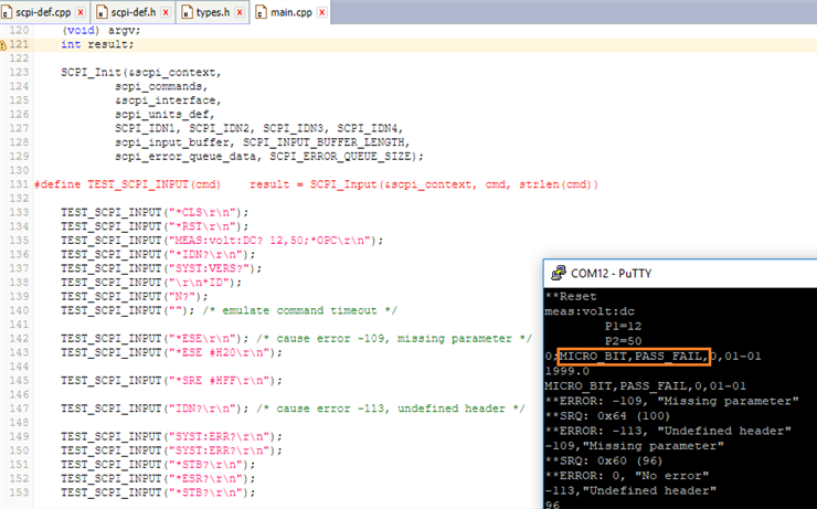
In the image above, you see MICRO_BIT and PASS_FAIL in the output.
Those are the values I programmed for the manufacturer and device name (the SCPI attributes for the *IDN? command).
That's it for the first program. My second project will try to read from the USB port.
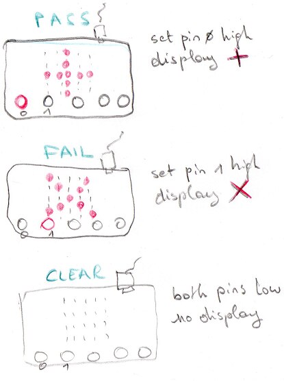
Figure: display and IO behaviour for all 3 states.
Second Firmware Version: SCPI Commands, USB and Display
The next version of the program has improved a few things.
The micro:bit is now listening for commands in sleep mode. Only when a character appears, it'll wake up and send that character to the SCPI parser.
#include "MicroBitSerial.h"
// ...
MicroBitSerial serial(USBTX, USBRX);
// ...
    while(1) { // the device goes into low power when no characters arrive
        character = serial.read(SYNC_SLEEP);
        SCPI_Input(&scpi_context, (const char *) (&character), 1);
    }
The SCPI output function is also using the serial class:
size_t SCPI_Write(scpi_t * context, const char * data, size_t len) {
    (void) context;
    return serial.send((uint8_t *)data, len);
}
To display the success and fail status, I've created two bitmaps. A plus and a cross drawing. I first tried to write these with the micro:bit built-in font, but did not like how the X is displayed.
MicroBitImage imgPass("0, 0, 255, 0, 0\n0, 0, 255, 0, 0\n255, 255, 255, 255, 255\n0, 0, 255, 0, 0\n0, 0, 255, 0, 0\n"); // plus
MicroBitImage imgFail("255, 0, 0, 0, 255\n0, 255, 0, 255, 0\n0, 0, 255, 0, 0\n0, 255, 0, 255, 0\n255, 0, 0, 0, 255\n"); // X
To control the device, I've written a single SCPI command that can set the state. Here is the syntax
[:INDicator:]STAte PASs
[:INDicator:]STAte FAIl
[:INDicator:]STAte CLEar
E.g.: you can send the STA PAS command to display the cross image.
The three possible states are defined as SCPI enumerators:
enum scpi_state_t {
    SCPI_STATE_PASS,
    SCPI_STATE_FAIL,
    SCPI_STATE_CLEAR
};

const scpi_choice_def_t scpi_state_def[] = {
    {/* name */ "PASs",      /* type */ SCPI_STATE_PASS  },
    {/* name */ "FAIl",      /* type */ SCPI_STATE_FAIL  },
    {/* name */ "CLEar",    /* type */ SCPI_STATE_CLEAR  },
    SCPI_CHOICE_LIST_END,
};
The SCPI command handler acts based on the requested state:
static scpi_result_t setState(scpi_t * context) {
int32_t param1;
scpi_bool_t result;
scpi_result_t retval;
result = SCPI_ParamChoice( context, scpi_state_def, ¶m1, TRUE );
if ( false == result )
{
return SCPI_RES_ERR;
}
else
{
switch (param1) {
case SCPI_STATE_PASS:
uBit.display.clear();
uBit.display.print(imgPass);
retval = SCPI_RES_OK;
break;
case SCPI_STATE_FAIL:
uBit.display.clear();
uBit.display.print(imgFail);
retval = SCPI_RES_OK;
break;
case SCPI_STATE_CLEAR:
uBit.display.clear();
retval = SCPI_RES_OK;
break;
default:
SCPI_ErrorPush(context, SCPI_ERROR_ILLEGAL_PARAMETER_VALUE);
retval = SCPI_RES_ERR;
}
}
return retval;
}
That handler is registered into the SCPI lib as follows:
{.pattern = "[:INDicator]:STAte", .callback = setState,},
video: initial test of the SCPI commands and the LED matrix
That's all that's needed to make this work. In the next version I'll add the GPIO functionality to pull a pin high at Pass or Fail.
Third and Final Firmware Version: Add GPIO
The final firmware version adds two output pins. Pin 0 on the micro:bit sets high on success. Pin 1 on failure status.
This requires little changes. In the main() function we set both pins to 0, just after initialising the board.
    // Initialise the micro:bit runtime.
    uBit.init();
    uBit.io.P0.setDigitalValue(0);
    uBit.io.P1.setDigitalValue(0);
Then, in the SCPI handler, based on the state, the appropriate pin is set:
        case SCPI_STATE_PASS:
            uBit.io.P1.setDigitalValue(0);
            uBit.io.P0.setDigitalValue(1);
            // ...
            break;
        case SCPI_STATE_FAIL:
            uBit.io.P0.setDigitalValue(0);
            uBit.io.P1.setDigitalValue(1);
            // ...
            break;
        case SCPI_STATE_CLEAR:
            uBit.io.P0.setDigitalValue(0);
            uBit.io.P1.setDigitalValue(0);
            // ...
            break;
The Mbed project is attached to this blog post.
LabVIEW Driver
The driver library contains the necessary blocks to control the micro:bit and an example process. This is also attached at the end of this blog post.
State Control block:
 | 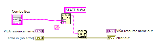 |
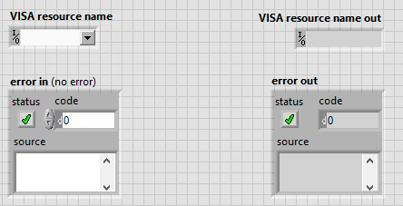
Initialize block:
 |
|

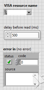
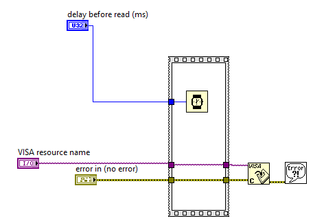
Reset block:
 | 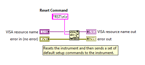 |
Default Setup block:
 | 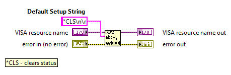 |
Close block:
 |  |
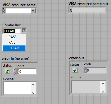
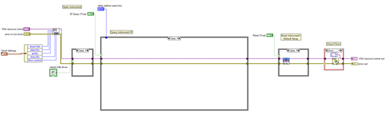
LabVIEW Example Process
I've used the simplest process that shows the micro:bit Pass / Fail device functions.
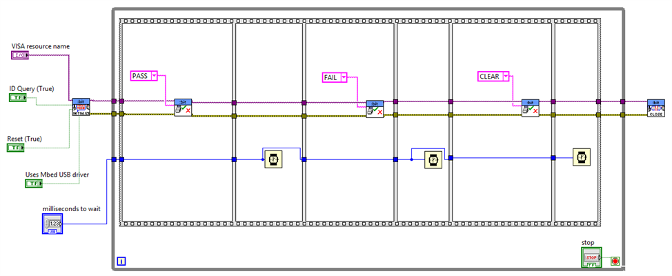
image: demo process runs through the three statuses of the micro:bit pass / fail device
Because it uses the driver's functional blocks, all is fairly easy.
It connects to the micro:bit over USB. Then it steps through PAS, FAIL and CLEAR status until you press the stop button. At the end the connection is closed and resources freed.
When you execute this flow, you can see the micro:bit LED matrix represent the statuses.
You can also measure the signals on pin 0 and 1 during the execution.
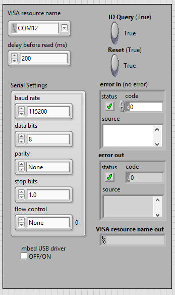
Before executing the process, select the COM port that's assigned to the micro:bit.
If you've installed the Mbed USB serial driver (Windows only, neccessary for Windows versions < 10), set the "Uses Mbed USB driver True. Else set this witch off.
You can see if the USB driver is the MBed one by opening the device manager, open the Ports node and check if the micro:bit entry says mbed serial.
If yes, you use the driver and youhave to flip the switch.

image: take care to select the COM port and USB driver of your micro:bit before starting.
In a real world process, the device is intended to be part of an automated test jig.
The state would be set based upon a successful or failed test.
The fail pin can be used to sound a horn or to drive a gizmo that kicks the device under test into a repair bin.
Source Code for micro:bit and LabView
The LabVIEW driver is attached as a ZIP archive below.
The source code can be imported and built by following these steps:
In Mbed, click import. Then click on the link to import from URL:

Enter https://os.mbed.com/users/jancumps/code/microbit_scpi_pass_fail/
Select these options:

After Import, you can select the project and press compile.
If all works OK, Mbed creates a hex file and places it in your Download folder.
If you drop that file on your micro:bit, it should be programmed as a Pass / Fail device.
You can test this by connecting to its COM port with PuTTY, 115200.
type STA PAS then enter (you don't see what you type)
It should show a + on the led matrix.
This is a WIP type of blog that will get updated each time I make progress finished blog. This Project14 theme runs until November 14. That’s the time I’ll give myself to complete this.
Top Comments