


 | Enter Your Electronics & Design Project for a chance to win a Grand Prize for Originality, a Tool Set, and a $100 Shopping Cart! | Project14 Home |
| Monthly Themes | ||
| Monthly Theme Poll |

This is the prototype for an inexpensive but reasonably accurate meter for measuring resistance in the milliohm range. The development was documented in detail and links can be found at the bottom of this post. The prototype is functional but still under development so continue to watch this space if you are interested in the final outcome.
Features
- Low cost
- Dual range covering from 1 milliohm to 40 ohms
- Choice of power source - USB or batteries
- Kelvin (4-wire) probes
- Temperature compensated precision current sources based on the LM334ZLM334Z
- Signal amplification based on the MCP6N16 instrument amp
- Low current (1 to 10 mA) through the Device Under Test (DUT)
- Provision for future "out of range" indication
- Provision for future auto ranging
- Better than 1 milliohm accuracy down to 1 milliohm
I have repurposed an old internet hub to house the meter.

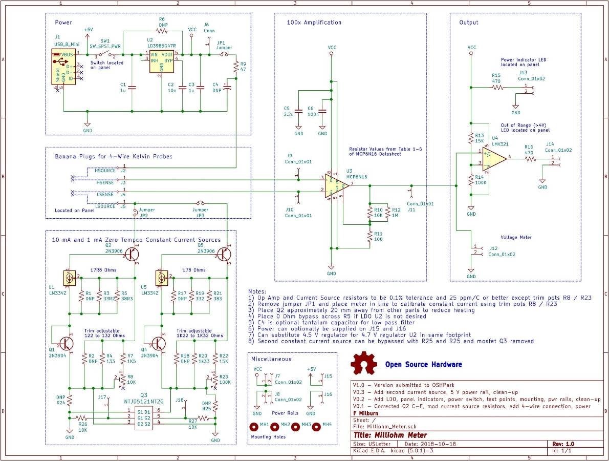
Schematic
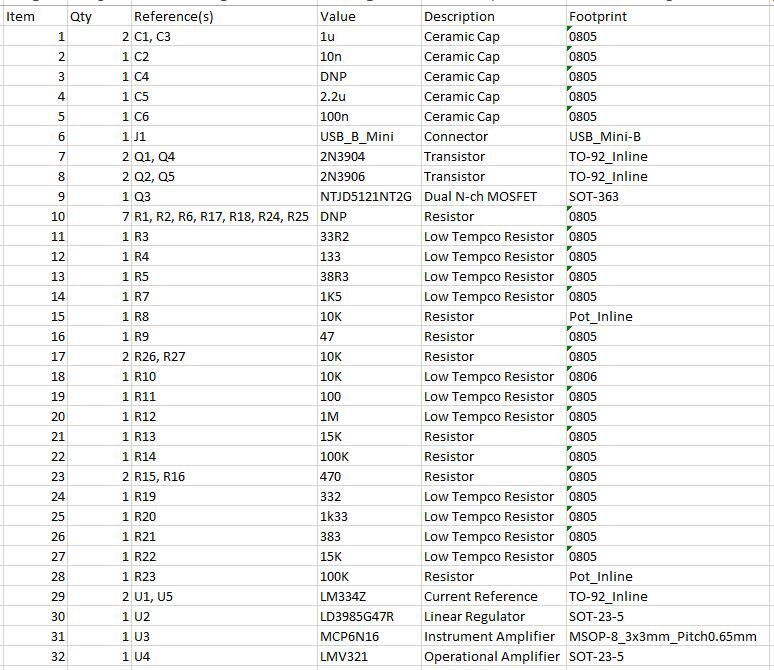
Bill of Materials
I have used a lot of precision low temperature coefficient parts but these may be overkill for many applications. There is a very interesting discussion around zero tempco constant current sources in the links at the end of this post.
PCB
The PCB has many surface mounted parts but was designed to be hand soldered. Small ICs should be soldered first, followed by the 0805 components, and then through hole. This is still under development but if you are interested in the gerbers files or Kicad files send me a personal message.

Calibration
The multi-turn potentiometers enable very accurate setting of the current sources.

Code
No code required at least for now. This is pure analog :-)
Using the Milliohm Meter
Potential Improvements
- MOSFET Q3 is for future auto-ranging but is not currently implemented.
- Op Amp U4 is configured as a comparator to flag out of range conditions but is not currently implemented.
- Trim Pots R8 and R23 may need additional trim resistors (R1, R2, R17, R18) to get in range
- Accuracy drops off below 3 milliohms
- User must add a 10x factor to readings when using the high range
Next Steps
I intend to continue working through the improvements and will post updates as appropriate. If you are interested in additional details, including design decisions and calculations see the related links below. I thank the following people for encouragement, helpful comments and direction during the development of this project: Shabaz, Gene Breniman, John Wiltrout, Michael Kellett, and Jon Clift As always, comments and corrections are appreciated.
Related Links
Testing Current Sources for a Kelvin (4-Wire) Milliohm Meter
More on Current Sources and a Kelvin (4-Wire) Milliohm Meter
Even More on Current Sources and a Kelvin (4-Wire) Milliohm Meter
Working Prototype of a Kelvin (4-Wire) Milliohm Meter
PCB for a Kelvin (4-Wire) Milliohm Meter
Change Log
10 Nov 2018: Corrected typo on range, added link to parts, added to features list
Top Comments