


I was scrolling through Amazon and ended up buying this the other day for $18 delivered.

Specifications
Input voltage range: DC5.0-30.0V (with reverse connection protection)
Load voltage range: DC1.5-25.0V (with reverse connection protection)
Load current range: 0.00-5.00A
Discharge power: 35W
Constant current precision: ±(1%+3digits)
Voltage precision: ±(0.5%+1digit)
Over voltage protection(OVP): default 25.2V (can be reset)
Over current protection(OCP): default 5.10A (can be reset)
Over power protection(OPP): default 35.5W (can be reset)
Low voltage protection(LVP): default 1.5V (can be reset)
Over temperature protection(OTP): default about 80℃(cannot be reset)
Fan rotation speed: 8000±10%RPM
I went down the rabbit hole looking at reviews and found a couple and a thread on the EEVBlog. Not mentioned above, but what caused me to buy it is that it can be controlled over serial. Besides, it was $18 and I can't even buy take-out pizza for the grandkids when they come to visit for that.
I didn't pay careful attention to the specifications before buying, but now that I have it, note the following:
- The minimum input voltage is poor (1.5V) so can't even discharge an alkaline cell with that
- The only mode is constant current
- The current increment settings are coarse at 0.01A
- The current resolution is low at 0.01A
- The current precision is poor considering it is 3 digits and resolution is 0.01A
Take it Apart
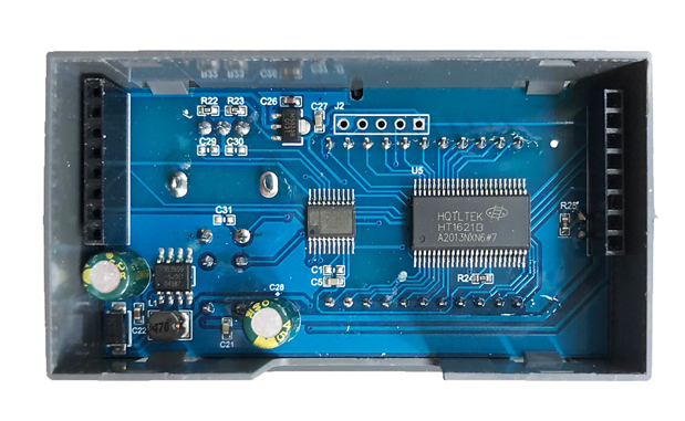
It arrived packaged nicely enough and undamaged. The enclosure is designed to be snapped into a panel and is open in the back. There are two PCBs sandwiched together with 0.1-inch headers that pull apart easily with no tools. The PCB on the back has the fan attached and a TIP122TIP122 BJT Darlington NPN transistor that serves as the load.

The PCB attached to the front has the microcontroller and a chip with the identification sanded off. It also has some solder spatter.
First Test
I powered it up with one benchtop power supply and provided the load with a second. I'm using 18AWG wire for connections. The power supply on the right is the one under load. It is a Multicomp Pro MP710086MP710086 that I have written about here on element14. In my tests, the current display with that power supply was accurate to within 0.5mA right down to 0 and the voltage display was pretty much bang on over the entire range.
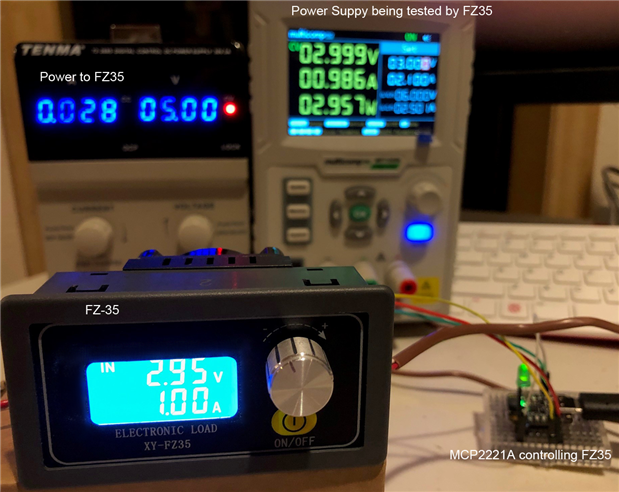
The electronic load can be powered by 5V and draws less than 30mA as can be seen by the power supply on the left. For the first tests, I manually set the control parameters with the simple user interface. The controls consist of a button to start and stop the load test and a rotary encoder with a push-button used to set parameters. The description of the parameters is a bit unusual but I got used to it and the manual control fairly quickly. For this first set of tests, I recorded the results in my notebook.
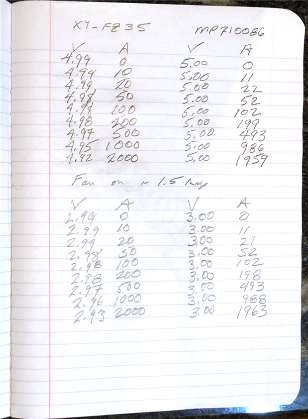
The two columns on the left are for the DC Electronic Load. The two columns on the right are the readings from the bench power supply which is thought to be pretty accurate. A couple of things to note:
- The fan seems to be controlled by current - it turns on at 1.5A
- Voltage measurement seems OK - there is a voltage difference (drop) but I'm not using Kelvin 4-wire measurement
- The current agreement isn't that great but meets the FZ35 specs (1% + 3digits) which aren't that great either
Serial Link
As noted above, my interest was the serial control. There is some discussion about this on the EEVBlog and at the bottom of the posts, there are two GitHub links. One is "copyrighted" and one only seems to have an executable. They seem to plot the voltage as a function of time with the electronic load set to a constant current. That is not what I want to do. I'd like to set the current and read the voltage from Python in the same script that I am controlling other instruments with SCPI.
To test that idea out I used an MCP2221A breakout board from Adafruit to talk to the FZ35. These only cost $6.50 and have the advantage of being 5V tolerant which is important because the FZ35 communicates at 5V. The serial connection is made on a 0.1-inch pitch header. Jumpers were then made between the MCP2221A and the FZ35: TX to RX, RX to TX, and GND to GND. The MCP2221A was connected to my Windows 10 PC over USB.
Data Sheet
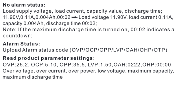
The commands must be sent and read in a rigid format. The commands are shown below.
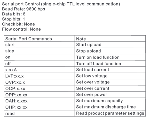
So for example, sending 1.0A does not work. 1.00A works. Sending OPP:5.00 does not work. OPP:05.00 works.
The only information we get in the datasheet for receiving data is this:
Python Script
I used PyCharm in the Anaconda suite for development. The script sets the protection parameters for the electronic load and then cycles through currents from 0.1A to 1.0A in 0.1A increments while reading the voltages and printing the results. Here is the code:
# MCP2221A with FZ35 Electronic Load
# Uses the MCP2221A to send commands to the constant current FZ35 Electronic Load
# Note that the commands must be sent in the exact format shown and byte encoded.
# Electronic load requires a pause after commands before reading (timing not fully investigated)
#
# This code is free to use by all
# Tested on Windows 10 machine with Python 3.8
# F Milburn Sept, 2021


import serial
import time


ser = serial.Serial(port='COM9', baudrate=9600, timeout=2)


# Set Protection
LVP = b'LVP:01.5'        # low voltage
OVP = b'OVP:06.0'        # over voltage
OCP = b'OCP:1.00'        # over current
OPP = b'OPP:06.00'       # over power
ser.write(LVP)
time.sleep(0.1)
ser.write(OVP)
time.sleep(0.1)
ser.write(OCP)
time.sleep(0.1)
ser.write(OPP)
time.sleep(0.1)
print(ser.read_all(), '\n')      # read setting success


# Vary current and read results
print('Voltage(V), Current(A)')
current = 0.0
for x in range(0, 10, 1):
    current = current + 0.1
    strCurrent = '{:.2f}'.format(current) + 'A'    # must be in exact format
    ser.write(strCurrent.encode('utf-8'))          # byte encoding
    time.sleep(0.1)
    ser.read_all()                                 # dummy read
    time.sleep(1)                                  # let things settle
    # check for valid input
    keepLooping = True
    while keepLooping:
        rawResult = (ser.read_all())
        time.sleep(0.1)
        if len(rawResult) > 5:
            if chr(rawResult[5]) == "V":
                result = rawResult.decode('utf-8')                      # decode it - make it a string
                result = result[:12]                                    # strip off end
                result = ''.join(i for i in result if not i.isalpha())  # strip alphabetic chars
                result = ''.join(i for i in result if i.isprintable())  # strip non-printable chars
                if result[0] == '0':
                    result = result[1:]                                 # strip off first zero if present
                print(result)
                keepLooping = False
            ser.flushInput()
I'm not a Pythonista so undoubtedly this could be improved. I'm not going to go through it line by line either but below are comments on some things that tripped me up initially.
- Serial is sent in byte format so there is some encoding and decoding prior to sending and after receiving. In some places, I used encode/decode and in others b'xxx'.
- It is necessary to give some time after issuing commands. I used 0.1 seconds.
- The FZ35 sends data every second or so and care must be taken to assure the data in the buffer is what is needed.
- The raw data read in needs some massaging prior to use.
Here is the resulting output.
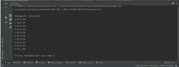
This output could be plotted in Python but I copy/pasted it into a spreadsheet.

Conclusion
This is not a particularly impressive pieced of test gear but then it only costs $18. And it works. I have had it running for a couple of days with no issues. The primary things I'd like to see improved are:
- Lower voltage capability down to below 1V
- Improved current accuracy and resolution to 1mA
I fooled around trying to make something similar DIY a while back but didn't complete the project. One of these days I will get back to that project or maybe even buy a better instrument. Thanks for reading, comments are always welcome.


