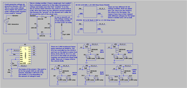
OK, here is an updated schematic; it is actually the exact same as before minus a pull-up resistor on the FETs. So how about I explain things a little more and maybe we can see what I messed up this time  .
.
So the FETs are P-Channel setup up as a low-side load. I like to use low-side because then I don't have power always on at the other end of the Drain. In this application, there is no power in the system at all unless it is being cranked, but it is just a habit, so I did it here. The LM3914 has open-collector outputs on the Lx pins. Because of this, the pins float when not "enabled" and are current sinks when they are. That is a 10k pull-up between the Gain and the Source on the FETs. When the Lx pin is not "enabled," the pin will float, which means it will be weak-pulled high to the voltage on the Source pin (15_V_2 in this case). When "enabled," The Gate will be pulled low, passing the 15_V_2 from the Source to the Drain; when this happens the bulbs will essentially be connected from 15V to ground, lighting them up.


Top Comments
-

jw0752
-
Cancel
-
Vote Up
+2
Vote Down
-
-
Sign in to reply
-
More
-
Cancel
-

garengllc
in reply to jw0752
-
Cancel
-
Vote Up
+2
Vote Down
-
-
Sign in to reply
-
More
-
Cancel
Comment-

garengllc
in reply to jw0752
-
Cancel
-
Vote Up
+2
Vote Down
-
-
Sign in to reply
-
More
-
Cancel
Children