element14 Community
element14 Community
    Register Log In
  • Site
  • Search
  • Log In Register
  • Community Hub
    Community Hub
    • What's New on element14
    • Feedback and Support
    • Benefits of Membership
    • Personal Blogs
    • Members Area
    • Achievement Levels
  • Learn
    Learn
    • Ask an Expert
    • eBooks
    • element14 presents
    • Learning Center
    • Tech Spotlight
    • STEM Academy
    • Webinars, Training and Events
    • Learning Groups
  • Technologies
    Technologies
    • 3D Printing
    • FPGA
    • Industrial Automation
    • Internet of Things
    • Power & Energy
    • Sensors
    • Technology Groups
  • Challenges & Projects
    Challenges & Projects
    • Design Challenges
    • element14 presents Projects
    • Project14
    • Arduino Projects
    • Raspberry Pi Projects
    • Project Groups
  • Products
    Products
    • Arduino
    • Avnet Boards Community
    • Dev Tools
    • Manufacturers
    • Multicomp Pro
    • Product Groups
    • Raspberry Pi
    • RoadTests & Reviews
  • Store
    Store
    • Visit Your Store
    • Choose another store...
      • Europe
      •  Austria (German)
      •  Belgium (Dutch, French)
      •  Bulgaria (Bulgarian)
      •  Czech Republic (Czech)
      •  Denmark (Danish)
      •  Estonia (Estonian)
      •  Finland (Finnish)
      •  France (French)
      •  Germany (German)
      •  Hungary (Hungarian)
      •  Ireland
      •  Israel
      •  Italy (Italian)
      •  Latvia (Latvian)
      •  
      •  Lithuania (Lithuanian)
      •  Netherlands (Dutch)
      •  Norway (Norwegian)
      •  Poland (Polish)
      •  Portugal (Portuguese)
      •  Romania (Romanian)
      •  Russia (Russian)
      •  Slovakia (Slovak)
      •  Slovenia (Slovenian)
      •  Spain (Spanish)
      •  Sweden (Swedish)
      •  Switzerland(German, French)
      •  Turkey (Turkish)
      •  United Kingdom
      • Asia Pacific
      •  Australia
      •  China
      •  Hong Kong
      •  India
      •  Korea (Korean)
      •  Malaysia
      •  New Zealand
      •  Philippines
      •  Singapore
      •  Taiwan
      •  Thailand (Thai)
      • Americas
      •  Brazil (Portuguese)
      •  Canada
      •  Mexico (Spanish)
      •  United States
      Can't find the country/region you're looking for? Visit our export site or find a local distributor.
  • Translate
  • Profile
  • Settings
The World in Motion
  • Challenges & Projects
  • Project14
  • The World in Motion
  • More
  • Cancel
The World in Motion
Blog Pulse Width Modulation a Speed Equalizer(3): Theory
  • Blog
  • Forum
  • Documents
  • Events
  • Polls
  • Files
  • Members
  • Mentions
  • Sub-Groups
  • Tags
  • More
  • Cancel
  • New
Join The World in Motion to participate - click to join for free!
  • Share
  • More
  • Cancel
Group Actions
  • Group RSS
  • More
  • Cancel
Engagement
  • Author Author: colporteur
  • Date Created: 29 Jul 2022 1:28 AM Date Created
  • Views 1376 views
  • Likes 8 likes
  • Comments 2 comments
  • motor projects
  • worldinmotionch
  • pwm
Related
Recommended

Pulse Width Modulation a Speed Equalizer(3): Theory

colporteur
colporteur
29 Jul 2022

Start with PWM

Let’s lay down some theory before we start the testing. A cycle is an interval of time during which a complete excursion of a value sequence is completed. In the drawing, the analog sine wave starts at 0V, rises to +5V, then falls to -5V and returns to zero. A cycle can also exist if a single polarity power supply is used.

image

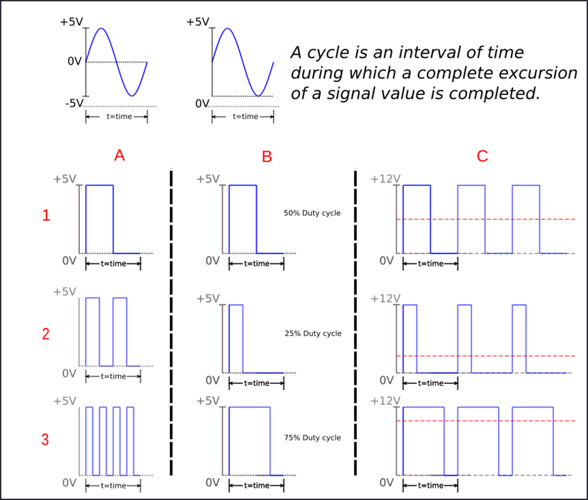
In the waveform column A, row 1, referred to as A1, the value of the digital signal in a time interval starts at 0V, rises to 5V for a period, then returns to 0V to complete the cycle. This complete excursion is one cycle of the digital signal. In waveform A2, in the same time period, two excursions of the digital signal have occurred. This would be two cycles. Similarly, waveform A3 shows four cycles of the digital signal occurring.

The time it takes for the digital signal value to complete one cycle is called the period of the digital signal. The number of cycles completed in one second is called frequency. Until 1965, the frequency was indicated in cycles per second.

Today, the more common technical term for the unit of measurement for frequency is Hertz, with the symbol Hz. You may have encountered Hertz in describing mains electrical power, or more likely the speed of a computer’s CPU (when measured in GHz).

The term ‘duty cycle’ refers to a comparison of the time interval at which the digital signal is high (5V) versus low (0V). If the digital pulse is high for 50 percent of the time interval, as in waveform B1, the digital signal has a duty cycle of 50 percent.

In waveform B2, the digital signal is high 25 percent of the time: a 25 percent duty cycle. Waveform B3 establishes a digital signal that is high for three-quarters of the time interval, so has a duty cycle of 75 percent.

By varying the duty cycle of the digital signal, the pulse width changes. Changing the width of the pulse is referred to as a Pulse Width Modulated digital signal.

Now let's take the PWM signal and apply it to an analog device like a DC motor. In waveform C1 the duty cycle of the PWM signal is 50%. The average voltage (indicated in red) would be half of the supply. Note in the drawing the voltage is +12V since it is the supply on the locomotive side of the L298N module. Waveform C2 is a 25% duty cycle so the average voltage would be lower still. In Waveform C3 the duty cycle is 75% therefore the average voltage supply to the motor would be higher.

Pulse width modulation is a technique that allows us to adjust the average value of the voltage that’s going to the electronic device by turning on and off the power at a fast rate.

Finish with L298N

The L298N is a motor driver module that provides both speed and direction control of a DC motor.  A motor driver module takes the low voltage input from a controller like Arduino and produces a voltage sufficient to drive the motor. The module can also control the direction of DC motors connected to the driver. The direction of DC motors is controlled by the logic signal sent to the motor driver module from the Arduino. This is all taken care of in the L298N driver library for the Arduino.

image

The L298N module contains an H-Bridge circuit. The integrated circuit contains four switching elements that can be transistors or MOSFETS.

image

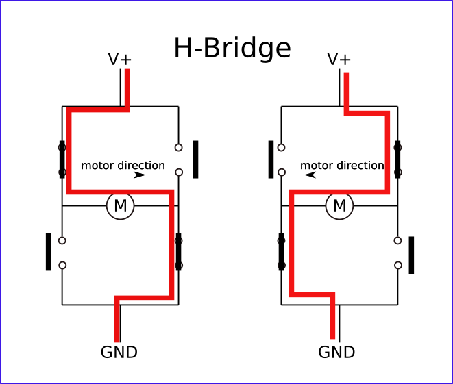
The logic signal applied to the circuit from the Arduino determines what switching elements are open and closed. By activating two particular switches at the same time we can change the direction of the current flow, thus changing the rotation direction of the motor.

The voltage supplied to the H-Bridge is the train voltage PWM signal. Recall the average of a PWM signal varies with the width of the pulse. If we combine the PWM and the H-Bridge, we can have speed control (PWM) and direction control (H-Bridge) over the DC motor.

  • Sign in to reply
  • colporteur
    colporteur over 2 years ago in reply to DAB

    Hey your insight gave me an idea. The train power supply has a switched labeled pulse. I wonder if this is for PWM from the supply. I will need to check. I can into some issues with PWM making the locomotive whine. It is documented in blog post 5. I'm trying to find a solution. Maybe the supply holds the key. Thanks!

    • Cancel
    • Vote Up 0 Vote Down
    • Sign in to reply
    • More
    • Cancel
  • DAB
    DAB over 2 years ago

    Takes me back a few decades when I bought an HO gage train to play with. 

    They introduced PWM as a way to have much better control for slowly moving your engine in more realistic train yard control.

    • Cancel
    • Vote Up 0 Vote Down
    • Sign in to reply
    • More
    • Cancel
element14 Community

element14 is the first online community specifically for engineers. Connect with your peers and get expert answers to your questions.

  • Members
  • Learn
  • Technologies
  • Challenges & Projects
  • Products
  • Store
  • About Us
  • Feedback & Support
  • FAQs
  • Terms of Use
  • Privacy Policy
  • Legal and Copyright Notices
  • Sitemap
  • Cookies

An Avnet Company © 2025 Premier Farnell Limited. All Rights Reserved.

Premier Farnell Ltd, registered in England and Wales (no 00876412), registered office: Farnell House, Forge Lane, Leeds LS12 2NE.

ICP 备案号 10220084.

Follow element14

  • X
  • Facebook
  • linkedin
  • YouTube